
System and method for performing remote welding operations on an apparatus

a technology of remote welding and remote welding, which is applied in the direction of process and machine control, program control, instruments, etc., can solve the problems of limiting the amount of time that the welder can perform welding operations, contaminating the controlled environment contained within the welding chamber, and compromising the design of the welding chamber

Active Publication Date: 2014-01-16
GENERAL ELECTRIC CO
View PDF12 Cites 49 Cited by
  • Summary
  • Abstract
  • Description
  • Claims
  • Application Information

AI Technical Summary

Benefits of technology

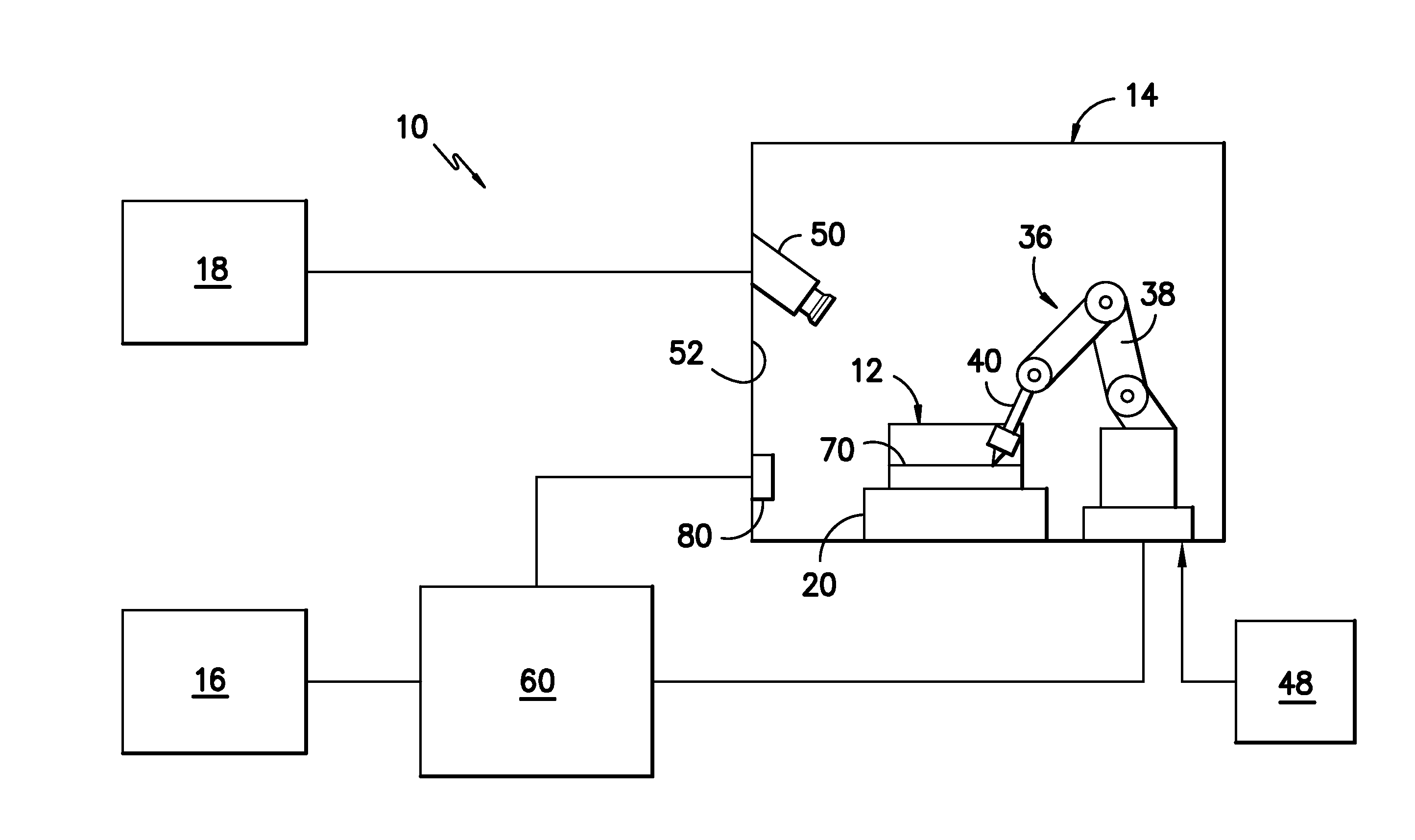
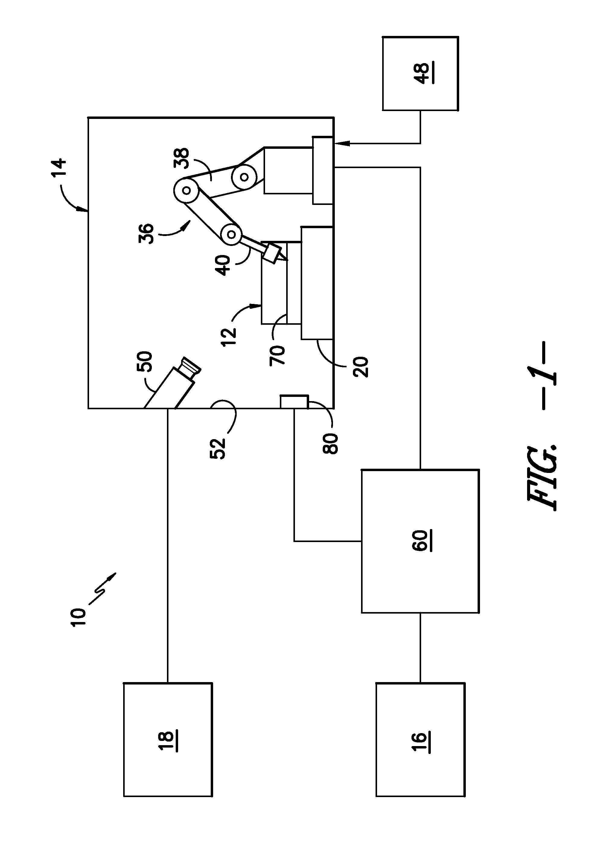
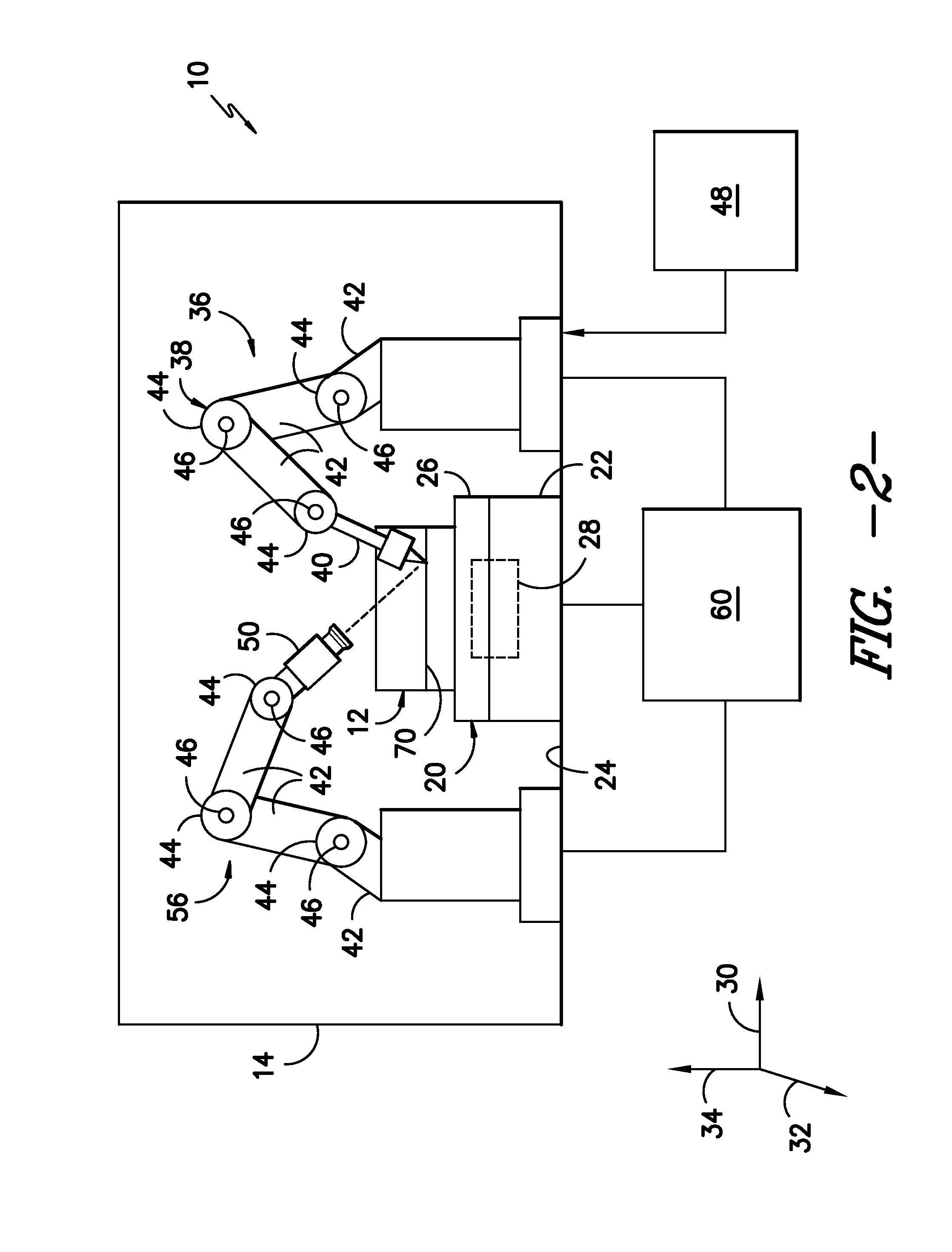
The present invention is directed to a system and method for remote welding operations on an apparatus. The system includes a welding chamber with a robotic welder and a welding simulation device outside the chamber. The welding simulation device performs a simulated welding operation based on the movements of the apparatus, and the robotic welder performs an actual welding operation based on the movements of the welding simulation device. The technical effect is to allow for remote welding operations to be performed on the apparatus with greater precision and efficiency.

Problems solved by technology

However, such access features typically result in a compromised design of the welding chamber.
For instance, air leaks often occur as a result of the access features, leading to contamination of the controlled environment contained within the welding chamber.
Moreover, when a welding chamber is heated, exposure to the heat can create a safety risk for the welder, thereby limiting the amount of time that the welder can perform welding operations within the welding chamber.

Method used


Image

  • System and method for performing remote welding operations on an apparatus
  • System and method for performing remote welding operations on an apparatus
  • System and method for performing remote welding operations on an apparatus

Examples


Embodiment Construction

[0013]Reference now will be made in detail to embodiments of the invention, one or more examples of which are illustrated in the drawings. Each example is provided by way of explanation of the invention, not limitation of the invention. In fact, it will be apparent to those skilled in the art that various modifications and variations can be made in the present invention without departing from the scope or spirit of the invention. For instance, features illustrated or described as part of one embodiment can be used with another embodiment to yield a still further embodiment. Thus, it is intended that the present invention covers such modifications and variations as come within the scope of the appended claims and their equivalents.

[0014]In general, the present subject matter is directed to a system and method for performing remote welding operations on an apparatus. In several embodiments, a welding simulation device, such as an actual or model welding torch, may be controlled by a u...


PUM

PropertyMeasurementUnit
movementsaaaaaaaaaa
movementaaaaaaaaaa
temperatureaaaaaaaaaa

Abstract

A system for performing remote welding operations on an apparatus is disclosed. The system may generally include a welding chamber configured to house the apparatus and a robotic welder positioned within the welding chamber. The robotic welder may be configured to perform an actual welding operation on the apparatus. In addition, the system may include a welding simulation device positioned outside the welding chamber and a controller communicatively coupled to the robotic welder and the welding simulation device. The welding simulation device may be configured to perform a simulated welding operation corresponding to the actual welding operation. The controller may be configured to track the movement of the welding simulation device and control the operation of the robotic welder based on the movements of the welding simulation device.

Description

FIELD OF THE INVENTION[0001]The present subject matter relates generally to a system and method for performing remote welding operations on an apparatus and, more particularly, to a system that utilizes a welding simulation device to control the motion of a robotic welder configured to perform welding operations on an apparatus positioned within a welding chamber.BACKGROUND OF THE INVENTION[0002]To perform welding operations on components formed from certain metals and alloys, the components must be placed in a controlled environment and / or must be heated to a relatively high temperature before and / or during the welding process. As a result, welding operations are often performed on such components within a welding chamber, wherein the environment can be closely monitored and controlled. For example, conventional welding chambers may be configured to be filled with an inert gas or other suitable gas in order to facilitate welding of the components contained therein. In addition, suc...

Claims


Application Information

Patent Timeline
Patent Type & Authority Applications(United States)
IPC IPC(8): B23K9/12
CPCB25J9/1689G05B2219/39387G05B2219/40169G05B2219/40195G05B2219/45104
Inventor HUNT, MARK LAWRENCE
Owner GENERAL ELECTRIC CO
Learn More