Method of inpsecting a substrate

a substrate and inspection method technology, applied in the field of substrate inspection, can solve the problems of increasing inspection time, height deviation among the plurality of divided regions, and inability to properly inspect the height of a target object, so as to reduce inspection time, enhance the reliability of the inspection module, and increase the inspection range of the substrate inspection apparatus

Active Publication Date: 2014-01-09
KOHYOUNG TECH
View PDF4 Cites 20 Cited by
  • Summary
  • Abstract
  • Description
  • Claims
  • Application Information

AI Technical Summary

Benefits of technology

[0032]According to the method described above, the height of the inspecting module in the target inspection region is adjusted by the height tendency information of at least one previous inspection region before inspecting the target inspection region, so that inspection range of the substrate-inspecting apparatus may be increased.
[0033]Further, when the inspection order of the inspecting regions is set along the lengthwise direction of the stage, the reliability of the inspecting module may be enhanced since height displacement is relatively small.
[0034]Further, a process of measuring inspection region by a laser range finder is not required to reduce the inspection time.
[0035]Further, when the inspection of the substrate is performed by using the first patterned light and the second patterned light of which wavelengths are different from each other, the inspection range of the substrate-inspecting apparatus may be increased comparing with the case using only one patterned light so that the reliability of inspection may be enhanced even through the substrate has severe warpage.
[0036]Further, according to an exemplary embodiment of the present invention, the dummy inspection regions are set between the inspection regions when the inspection regions are widely spaced apart from each other, so that the height displacement of the target inspection region may be more precisely estimated.
[0037]Further, according to an exemplary embodiment, the z-axis height of the camera is adjusted by an amount of height displacement of the camera, which is induced by the substrate transferor such as a tray or a jig, when the substrate is transferred by the substrate transferor, so that the reliability of the inspection may be more enhanced.

Problems solved by technology

Therefore, in case of a large sized substrate, the substrate may have warpage, so that there exists a height deviation among the plurality of divided regions.
Therefore, when the height deviation induced by the warpage of the substrate exceeds the tolerance, the height of a target object cannot be inspected properly.
However, the above method increases inspection time.

Method used


Image

  • Method of inpsecting a substrate
  • Method of inpsecting a substrate
  • Method of inpsecting a substrate

Examples


Embodiment Construction

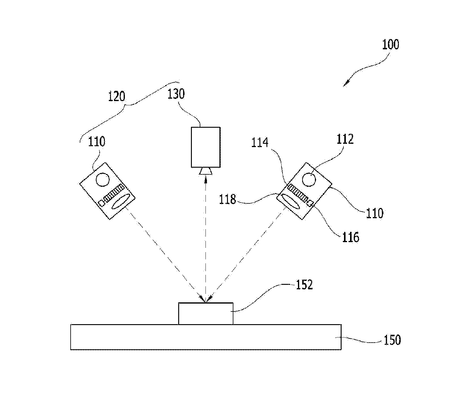
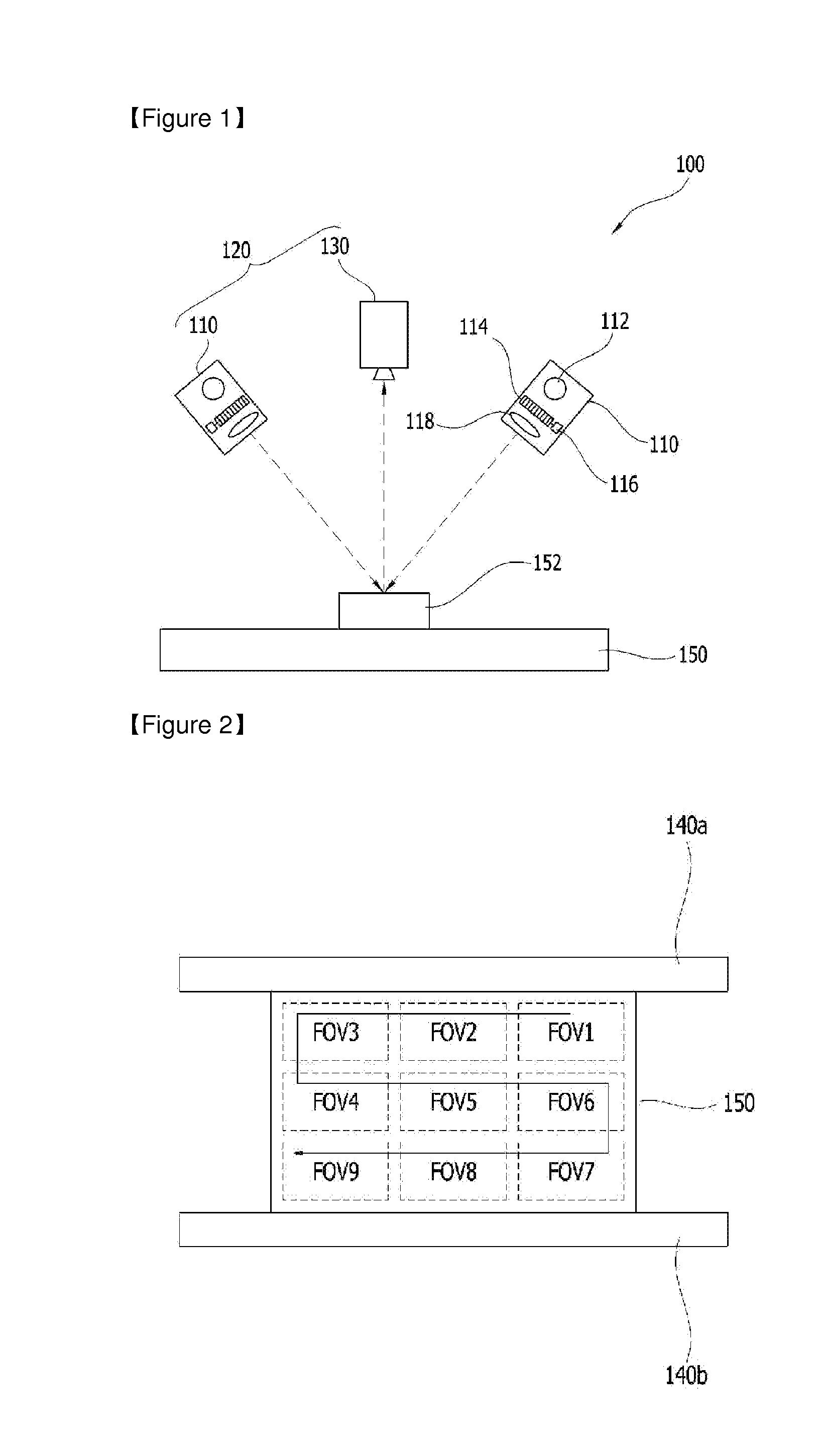
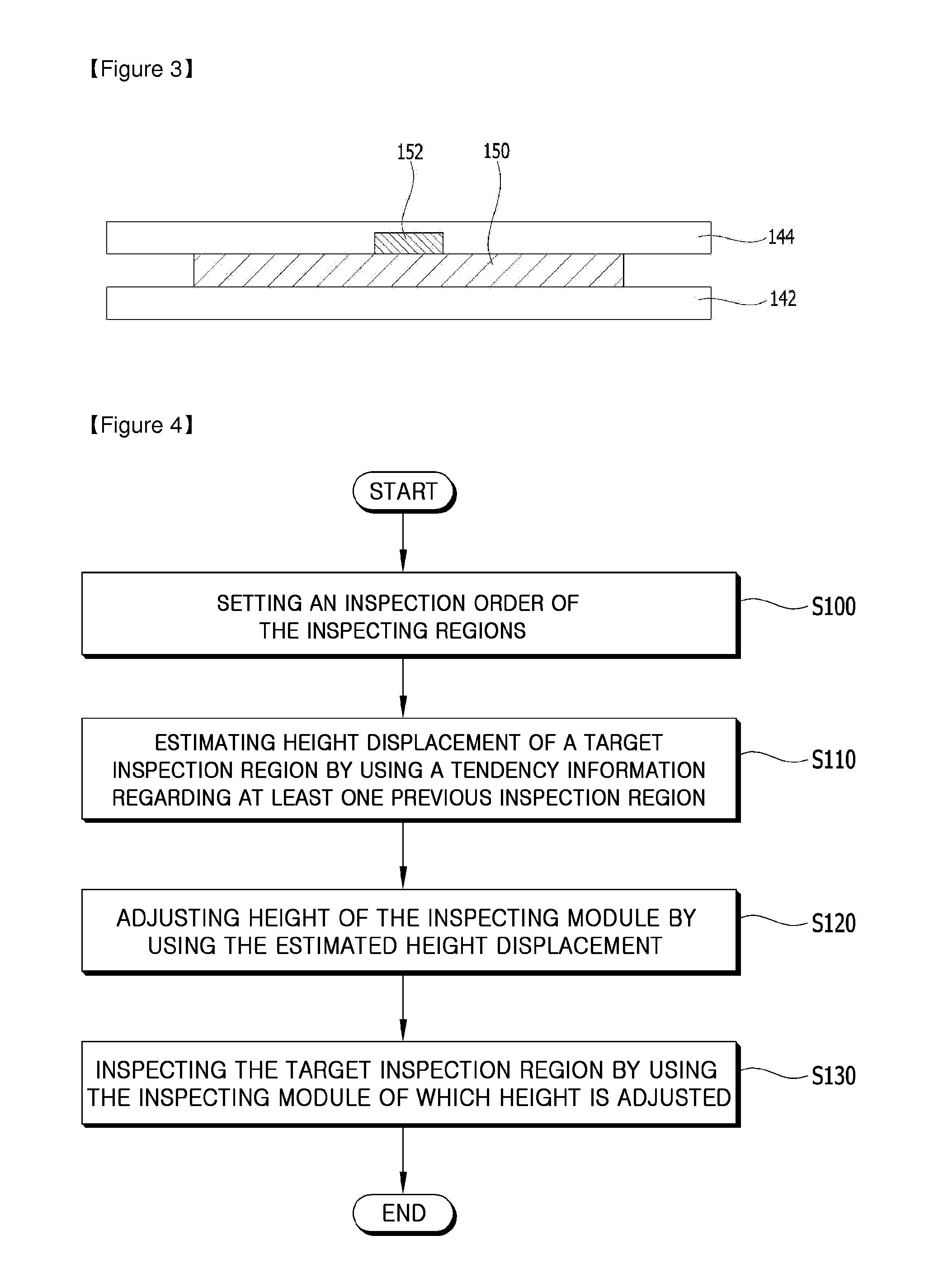
[0054]The present invention is described more fully hereinafter with reference to the accompanying drawings, in which example embodiments of the present invention are shown. The present invention may, however, be embodied in many different forms and should not be construed as limited to the example embodiments set forth herein. Rather, these example embodiments are provided so that this disclosure will be thorough and complete, and will fully convey the scope of the present invention to those skilled in the art. In the drawings, the sizes and relative sizes of layers and regions may be exaggerated for clarity.

[0055]It will be understood that, although the terms first, second, third etc. may be used herein to describe various elements, components, regions, layers and / or sections, these elements, components, and / or sections should not be limited by these terms. These terms are only used to distinguish one element, component, region, layer or section from another region, layer or secti...


PUM

PropertyMeasurementUnit
height displacementaaaaaaaaaa
heightaaaaaaaaaa
surface equationaaaaaaaaaa

Abstract

A method of inspecting a substrate is disclosed. The method is performed by a substrate-inspecting apparatus having at least one projecting module projecting a patterned light onto a substrate fixed on a stage and an inspecting module with a camera capturing an image, and inspecting a plurality of inspection regions of the substrate step by step. The method comprises, setting an inspection order of the inspecting regions according to a lengthwise direction of the substrate, estimating height displacement of a target inspection region by using a tendency information regarding at least one previous inspection region that is already inspected, adjusting height of the inspecting module by using the estimated height displacement of the target inspection region, and inspecting the target inspection region by using the inspecting module of which height is adjusted. Therefore, inspection time is reduced.

Description

TECHNICAL FIELD[0001]Exemplary embodiments of the present invention relate to a method of inspecting a substrate. More particularly, exemplary embodiments of the present invention relate to a method of inspecting a substrate, which is capable of enhancing a reliability of inspecting a status of a target object formed on a substrate.BACKGROUND ART[0002]In general, a target object is inspected whether the target object is properly formed before and after the target object is formed on a substrate, in order to enhance a reliability of the substrate having the target object formed thereon. For example, a solder paste formed on a substrate is inspected before an electronic device is mounted on the substrate through the solder paste, or an electronic device is inspected whether the electronic device is properly mounted on a substrate after the electronic device is mounted on the substrate through a solder paste.[0003]Recently, a three dimensional inspecting method using a substrate-inspec...

Claims


Application Information

Patent Timeline
Patent Type & Authority Applications(United States)
IPC IPC(8): G01N21/95
CPCG01N21/9501G01B11/0608G01B11/25
Inventor CHO, SOO-YOUNGYOU, HEE-WOOKHWANG, BONG-HAKIM, HEE-TAE
Owner KOHYOUNG TECH
Why Eureka
Try Eureka