
Printing material supply system and cartridge

Active Publication Date: 2014-01-09
SEIKO EPSON CORP
View PDF6 Cites 12 Cited by
  • Summary
  • Abstract
  • Description
  • Claims
  • Application Information

AI Technical Summary

Benefits of technology

The patent text discusses the need for improvements in cartridges used for supplying printing material or other liquids to a printing device. The technical effects of the patent text include reducing the size, lowering the cost, reducing the use of resources, increasing ease of manufacture, and improving usability of the cartridge. These improvements can be applied to a device other than the cartridge.

Problems solved by technology

When at least one of the plurality of printing material supply ports is deviated to the predetermined position in the printing device, generation of various faults are considered such as, for example, defects in the supply of the printing material, supplying of a type of printing material which is not intended, and damage to the printing device or the cartridge.
Here, the problems described above are not limited to printing material supply systems supplying a printing material from a cartridge to a printing device but are common to liquid supply systems supplying other liquids from a cartridge to a liquid consumption device.
According to the cartridge of the aspect, it is not possible to mount the cartridge on the printing device due to the cartridge abutting against the partition plate, when the groove section in the cartridge deviated from a position of a partition plate in the printing device.

Method used


Image

  • Printing material supply system and cartridge
  • Printing material supply system and cartridge
  • Printing material supply system and cartridge

Examples


first embodiment

A-7. Modified Example of First Embodiment

[0217]In the cartridge 20 of the embodiment described above, the optical element 270 is provided on the first surface 201 in a position which cuts across the plane CXa but the optical element 270 may be provided on the first surface 201 in a position which cuts across the plane CXb or respective optical elements 270 may be provided in respective positions in the first surface 201 which cut across the plane CXa and the plane CXb.

[0218]In the cartridge 20 of the embodiment described above, the board side latching section 210 is provided on the third surface 203 in a position which cuts across the plane CXa but the board side latching section 210 may be provided on the third surface 203 in a position which cuts across the plane CXb or respective board side latching sections 210 may be provided on the third surface 203 in respective positions which cut across the plane CXa and the plane CXb.

[0219]In the cartridge 20 of the embodiment described ab...

second modified example

B. Second Modified Example

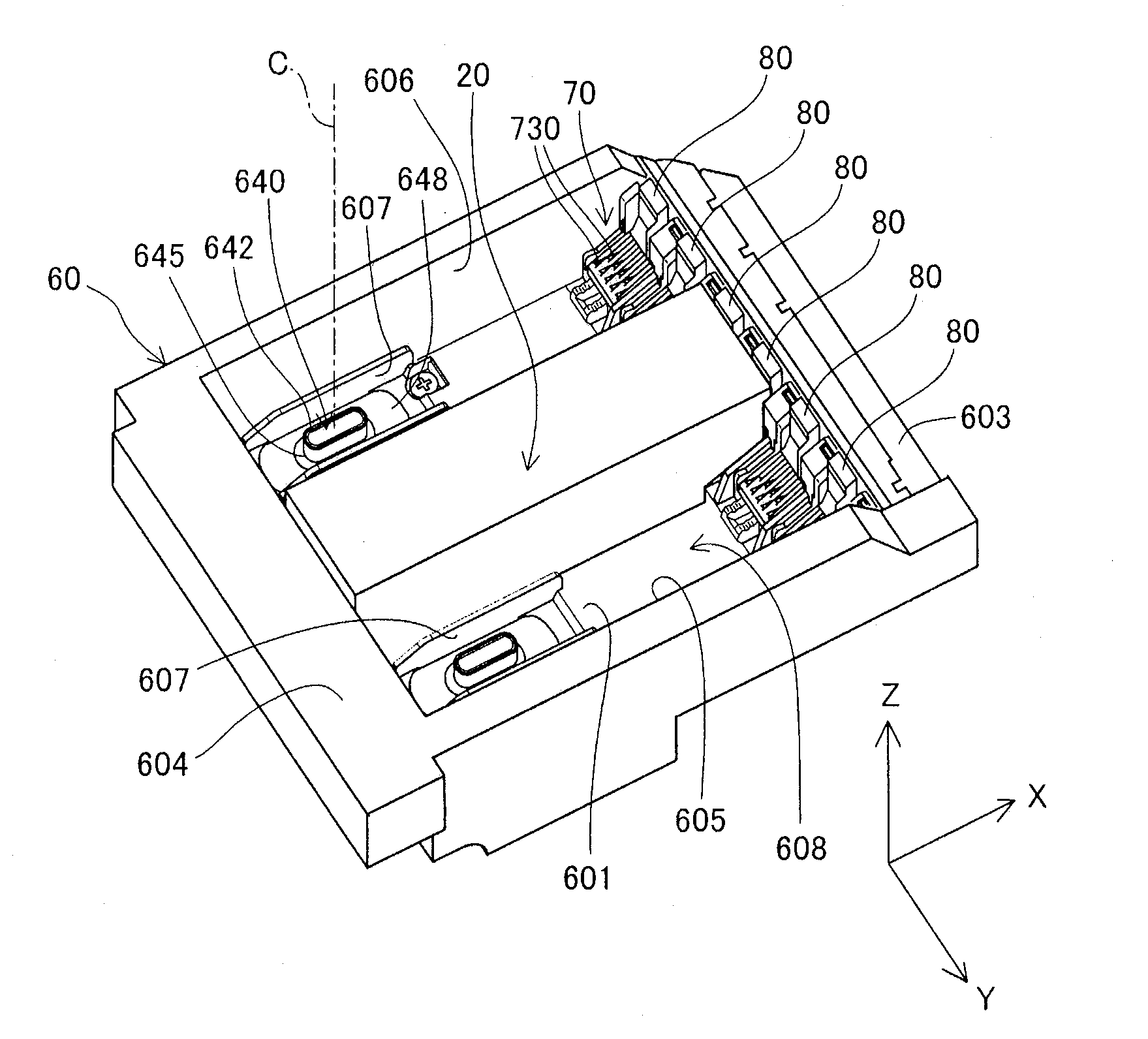
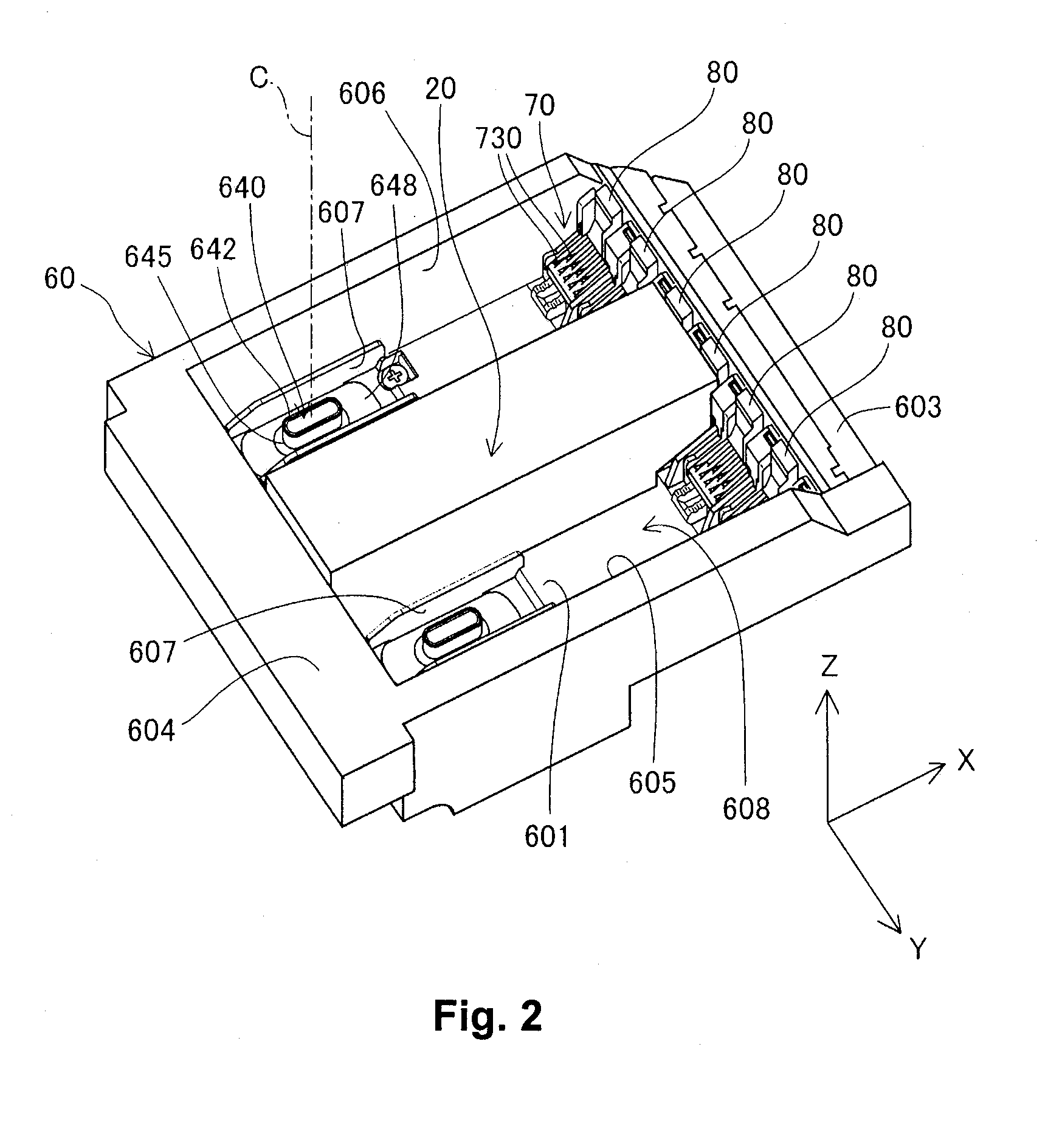
[0221]FIG. 29 is a perspective diagram illustrating a configuration of a cartridge 21 according to a second embodiment. The second embodiment is the same as the first embodiment excluding the point where a cartridge 21 which is not provided with the supply port side latching section 220 is used. In the explanation of the second embodiment, the same reference numerals will be given to the configurations which are the same as the first embodiment and the description thereof will be omitted. The cartridge 21 of the second embodiment is the same as the cartridge 20 of the first embodiment excluding the point that the supply port side latching section 220 is not provided. The cartridge 21 is latched to the holder 60 by the board side latching section 210 and the supply port side latching section 230.

[0222]According to the second embodiment, it is possible to prevent positional deviation of the two ink supply ports 280 to the holder 60 when the cartridge 21 is mo...

third modified example

C. Third Modified Example

[0224]FIG. 30 is a perspective diagram illustrating a configuration of a cartridge 22 according to a third embodiment. The third embodiment is the same as the first embodiment excluding the point where a cartridge 22 where the supply port side latching section 230 is not provided is used. In the explanation of the third embodiment, the same reference numerals will be given to the configurations which are the same as the first embodiment and the description thereof will be omitted. The cartridge 22 of the third embodiment is the same as the cartridge 20 of the first embodiment excluding the point that the supply port side latching section 230 is not provided. The cartridge 22 is latched to the holder 60 by the board side latching section 210 and the supply port side latching section 220.

[0225]According to the third embodiment, it is possible to prevent positional deviation of the two ink supply ports 280 to the holder 60 when the cartridge 22 is mounted on th...


PUM


Abstract

The cartridge comprises a plurality of printing material supply ports. The plurality of printing material supply ports are projecting from a first surface in a −Z axial direction to correspond to each of a plurality of printing material supply pipes provided on the printing device. A groove section is provided to be concave more to a +Z axial direction side than the first surface, and provided between two of the printing material supply ports adjacent to each other. The groove section receives the partition plate when the printing material supply ports are connected to the printing material supply pipes.

Description

CROSS-REFERENCE TO RELATED APPLICATIONS[0001]This application claims priority to Japanese Patent Application No. 2012-152290 filed on Jul. 6, 2012. The entire disclosure of Japanese Patent Application No. 2012-152290 is hereby incorporated herein by reference.BACKGROUND[0002]1. Technical Field[0003]The present invention relates to a printing material supply system and a cartridge thereof.[0004]2. Related Art[0005]In a printing material supply system, a cartridge is mounted on a printing device, the cartridge supplies a printing material to the printing device, and the printing device executes printing using the printing material. Such a cartridge comprises a printing material containing section and a printing material supply port, the printing material is contained in the printing material containing section, and the printing material is supplied to the printing device through the printing material supply port. A cartridge provided with a plurality of printing material supply ports ...

Claims


Application Information

Patent Timeline
IPC IPC(8): B41J2/175
CPCB41J2/17553B41J2/1753
Inventor NOZAWA, IZUMIKOBAYASHI, ATSUSHIMIZUTANI, TADAHIRO
Owner SEIKO EPSON CORP
Learn More