
Rotating electrical machine

a technology of rotating electrical machines and electrical components, which is applied in the direction of shafts, bearings, dynamo-electric components, etc., can solve the problems that the rotating electrical machines disclosed in patent document 1 are not configured to be satisfactorily small, and achieve the effect of enhancing the effect of integrally holding the housing and the flange, eliminating or reducing the size of the fixing screw

Inactive Publication Date: 2014-01-09
HITACHI AUTOMOTIVE SYST LTD
View PDF4 Cites 8 Cited by
  • Summary
  • Abstract
  • Description
  • Claims
  • Application Information

AI Technical Summary

Benefits of technology

The technical effect of the patent is to provide a small rotating electrical machine that is exceptionally quieteven compared to its size. This is achieved by pushing the rotor shaft in one direction with a preload imparting member, which suppresses abnormal noise caused by backlash of the rotor shaft in the axial direction. Additionally, by using a retaining force to make the housing and flange close to each other, the need for a fixing screw to fix the housing and flange can be eliminated or reduced, resulting in a smaller outer shape of the rotating electrical machine.

Problems solved by technology

However, the rotating electrical machine disclosed in Patent Document 1 is not configured to be satisfactorily small for the reasons described below.

Method used


Image

  • Rotating electrical machine
  • Rotating electrical machine
  • Rotating electrical machine

Examples


Embodiment Construction

[0028]Embodiments of the present invention will be described in detail below with reference to the drawings. The present invention, however, is not limited to the embodiments described below, and includes various modifications and applications within the technical concept of the present invention.

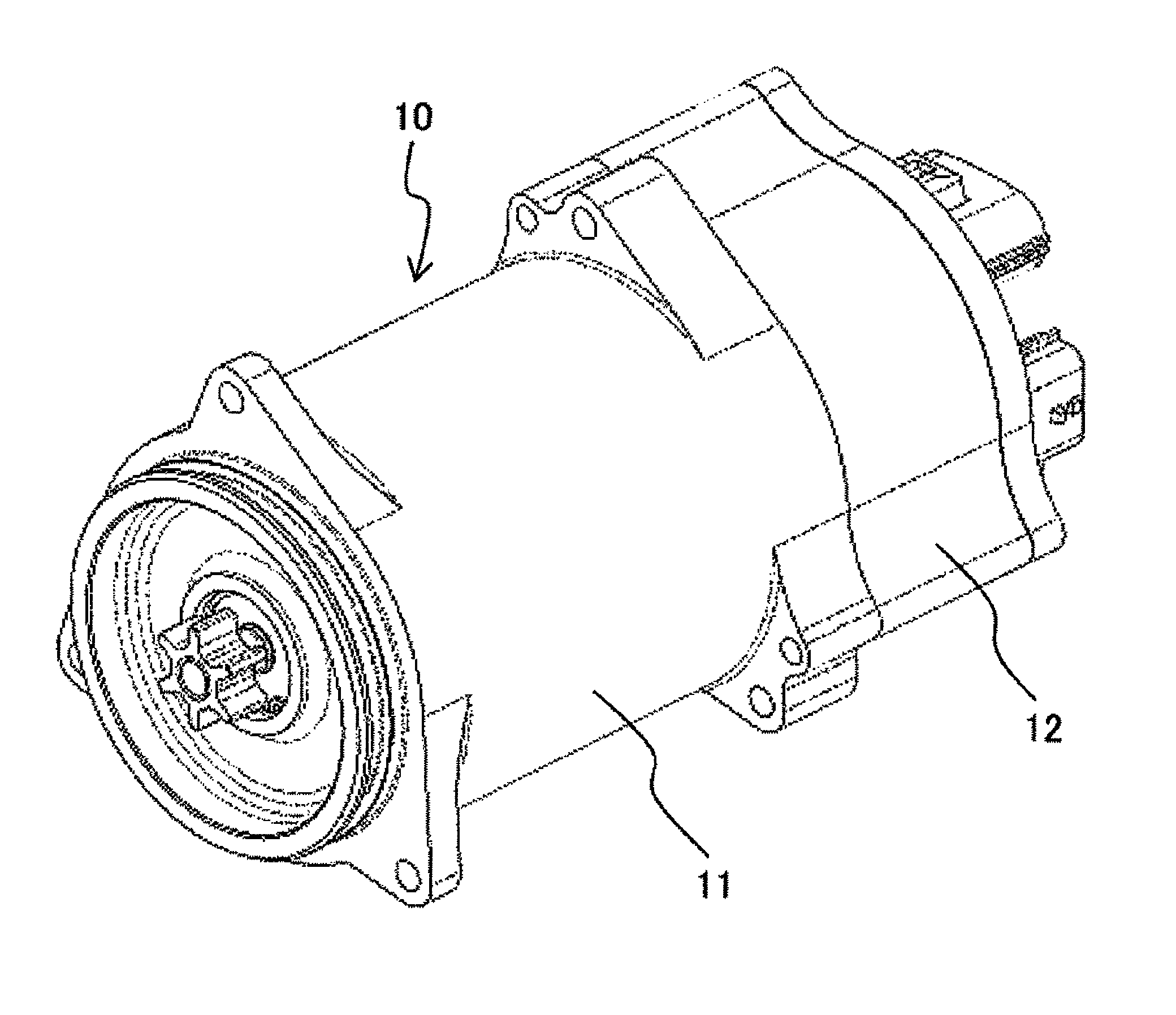
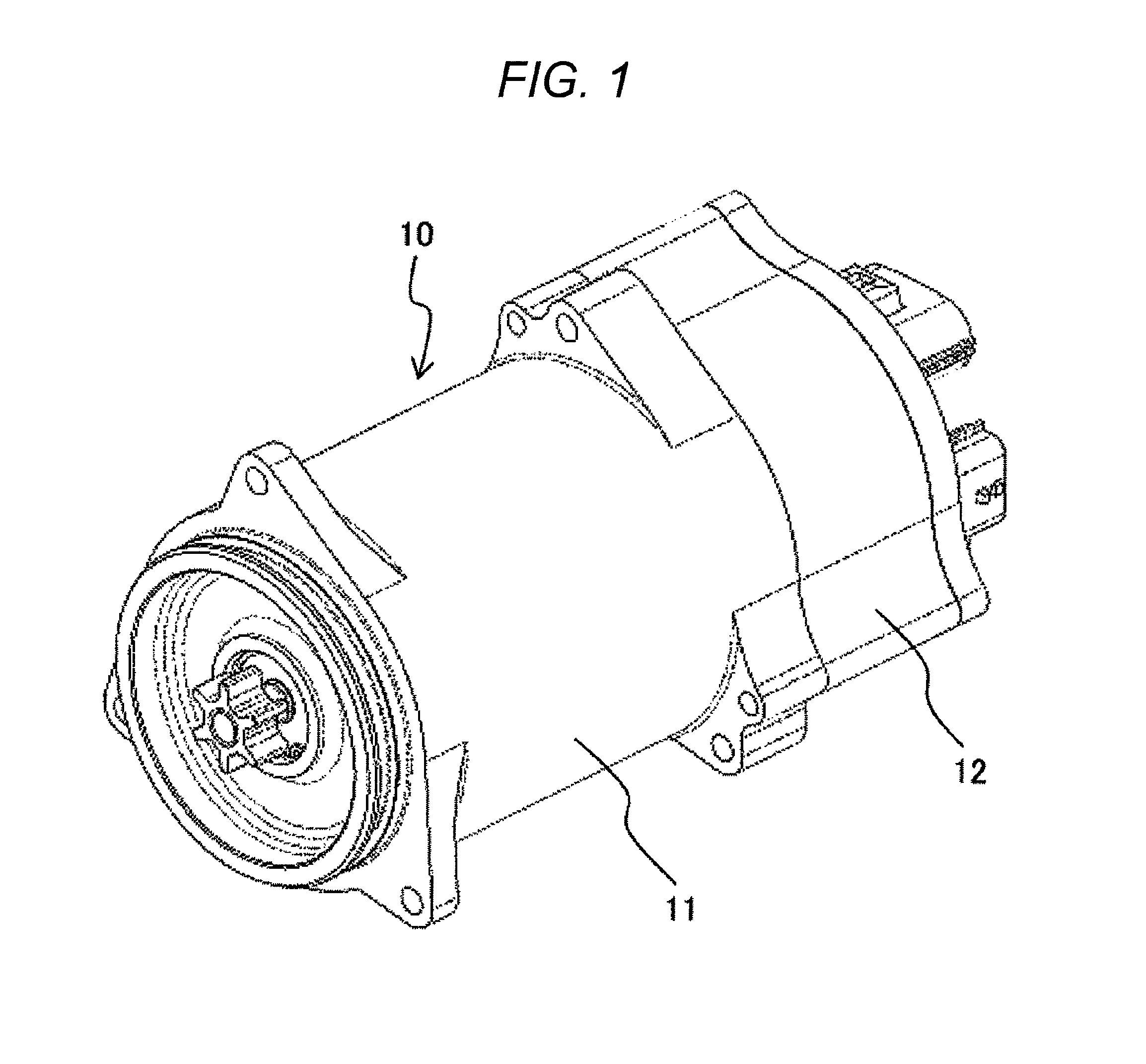
[0029]FIG. 1 is a view of a rotating electrical machine assembly 10 used in an electric power steering device as an example. The rotating electrical machine assembly 10 includes a rotating electrical machine 11 and an inverter controller 12 for controlling the driving of the rotating electrical machine 11.

[0030]The inverter controller 12 includes, inside a chassis thereof, a power semiconductor element constituting an inverter circuit, a drive circuit for driving the power semiconductor element, and a control circuit for controlling the drive circuit.

[0031]The rotating electrical machine 11 and the inverter controller 12 are firmly fixed to each other with a dedicated fixing bolt. In this s...


PUM


Abstract

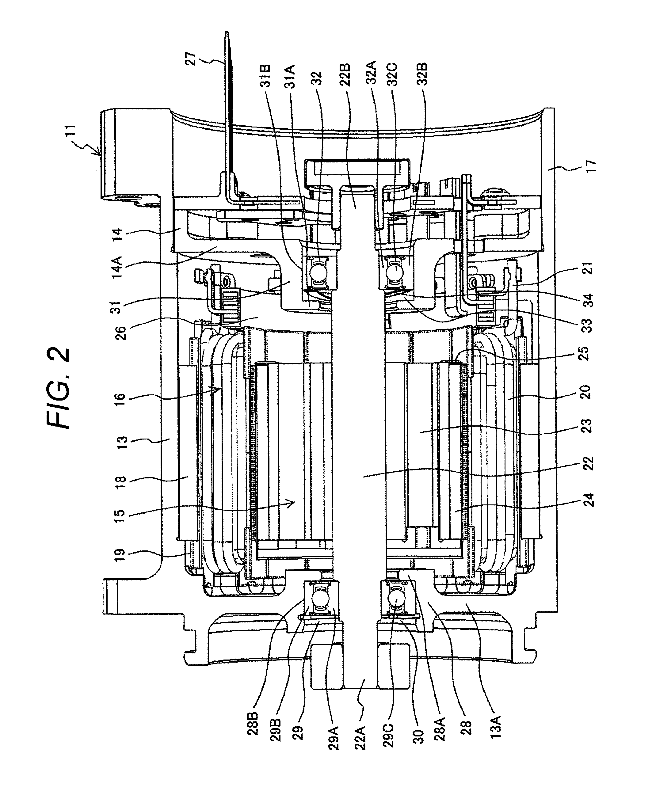
Inner rings of bearings arranged at both ends of a rotor shaft are fixed to the rotor shaft, and outer rings of both of the bearings are arranged at bearing holding parts movably in an axial direction of the rotor. A preload imparting member is attached to one of the bearings, the preload imparting member being configured to bias the rotor shaft in one direction and to apply a biasing force to make a housing and a flange, which constitute a chassis, come close to each other.

Description

BACKGROUND OF THE INVENTION[0001]1. Field of the Invention[0002]The present invention relates to a rotating electrical machine, and particularly to a rotating electrical machine with both ends of a rotor shaft thereof supported by bearings.[0003]2. Description of the Related Art[0004]Rotating electrical machines such as motors and generators have been used in many industrial fields. As a social trend, rotating electrical machines capable of saving energy and resources have been demanded. Therefore, many improvement technologies have been proposed to meet the demand for saving energy and resources. As a major technological subject of saving energy and resources, there is a technology for reducing the size or weight of a rotating electrical machine.[0005]For example, an in-vehicle rotating electrical machine of an automobile or the like is preferably small with excellent quietness and mountability, not to mention output performance.[0006]More specifically, a rotating electrical machin...

Claims


Application Information

Patent Timeline
Patent Type & Authority Applications(United States)
IPC IPC(8): H02K5/16
CPCH02K5/161H02K5/1732F16C25/083F16C2380/26F16C19/06
Inventor KAWASAKI, SHOZONAKATSUGAWA, JUNNOSUKENAKAYAMA, KENJIKANAZAWA, HIROSHIHAMADA, YASUNAGA
Owner HITACHI AUTOMOTIVE SYST LTD
Learn More