Vortex compressor as well as fixed vortex member and movable vortex member

A technology of scroll compressors and fixed scrolls, which is applied in the field of scroll compressors, can solve the problems of affecting the performance of the compressor refrigeration system, deteriorating the reliability of the compressor, and increasing the manufacturing cost, so as to improve the energy efficiency ratio and work efficiency. Stability, avoiding complex manufacturing process, suppressing the effects of high noise problems

Active Publication Date: 2014-12-24
EMERSON CLIMATE TECH (SUZHOU) CO LTD
View PDF7 Cites 4 Cited by
  • Summary
  • Abstract
  • Description
  • Claims
  • Application Information

AI Technical Summary

Problems solved by technology

However, in the case of using a silencer, it is generally only possible to suppress noise in a partial frequency range of the entire frequency band (such as high-frequency noise)
Moreover, due to the placement of the muffler, it also causes a pressure drop which adversely affects the performance of the compressor and the entire refrigeration system
In addition, additionally providing a muffler complicates the manufacturing process due to an increase in the number of parts, increases the manufacturing cost, and requires an additional installation space for the muffler, and also degrades the operational reliability of the compressor accordingly.

Method used


Image

  • Vortex compressor as well as fixed vortex member and movable vortex member
  • Vortex compressor as well as fixed vortex member and movable vortex member
  • Vortex compressor as well as fixed vortex member and movable vortex member

Examples


Embodiment Construction

[0035] The invention will be described in detail below by means of exemplary embodiments with reference to the drawings. The following detailed description of the present invention is for the purpose of illustration only, and in no way limits the present invention and its application or use.

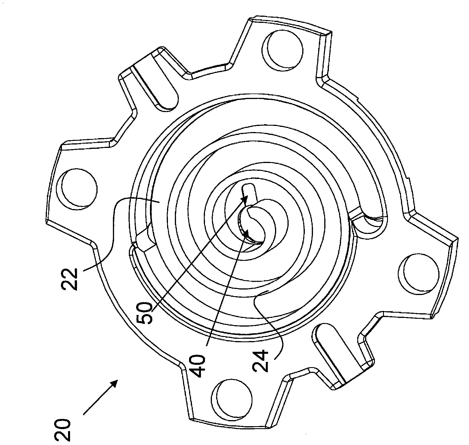
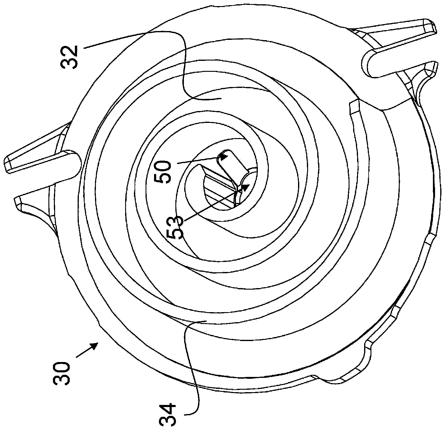
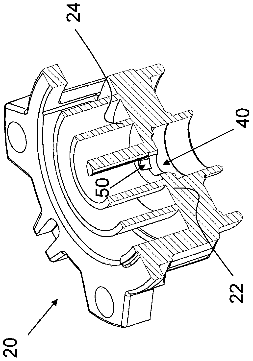
[0036] First, refer to Figure 1 to Figure 7 The structure of the compression mechanism of the scroll compressor according to the first embodiment of the present invention is described, in which figure 1is a perspective view showing a fixed scroll member of a compression mechanism according to a first embodiment of the present invention, figure 2 is a perspective view showing an orbiting scroll member of a compression mechanism according to a first embodiment of the present invention, image 3 is a longitudinally sectional perspective view showing a fixed scroll member according to a first embodiment of the present invention, Figure 4 is a longitudinally sectional perspective view ...


PUM


Abstract

The invention discloses a vortex compressor as well as a fixed vortex member and a movable vortex member. On the one hand, the vortex compressor comprises a compression mechanism, an exhaust port and an emission space, wherein the compression mechanism comprises a fixed vortex member and a movable vortex member, the fixed vortex member comprises a fixed vortex end plate and a fixed vortex roll, the movable vortex member comprises a movable vortex end plate and a movable vortex roll, and the fixed vortex roll and the movable vortex roll are combined together to limit a plurality of compression chambers including first compression chambers and second compression chambers; the exhaust port is suitable for communicating with the first compression chambers; and the emission space is suitable for communicating with the exhaust port. The first compression chambers, the exhaust port and the emission space form a high-pressure area. The vortex compressor also comprises a communicating passage which is set to ensure that at least one of the second compression chambers and the high-pressure area can be communicated with each other before a vortex roll separation point. According to the invention, the pressure of the first / center compression chambers can be changed more gently, so that the problem of high noise can be effectively solved, and the energy efficiency ratio and working stability of the compressor can be improved.

Description

technical field [0001] The present invention relates to a scroll compressor and a fixed scroll member and a movable scroll member, and more particularly, to a scroll compressor having an improvement in pressure fluctuation of a central compression chamber. Background technique [0002] A scroll compressor includes a compression mechanism composed of a fixed scroll member and a movable scroll member. The fixed scroll member includes a substantially helical fixed scroll extending from an end plate thereof, and the orbiting scroll member includes a substantially helical orbiting scroll extending from an end plate thereof. The fixed spiral scroll and the movable spiral scroll engage with each other to define a plurality of closed crescent-shaped compression chambers therebetween. The movable scroll is driven by, for example, an electric motor so as to perform translational rotation relative to the fixed scroll (that is, the axis of the movable scroll revolves with respect to th...

Claims


Application Information

Patent Timeline
IPC IPC(8): F04C18/02F04C29/12
Inventor 崔永华范忆文韩艳春
Owner EMERSON CLIMATE TECH (SUZHOU) CO LTD
Why Eureka
Try Eureka