
Pillar trim structure

Active Publication Date: 2013-11-28
SUZUKI MOTOR CORP
View PDF2 Cites 5 Cited by
  • Summary
  • Abstract
  • Description
  • Claims
  • Application Information

AI Technical Summary

Benefits of technology

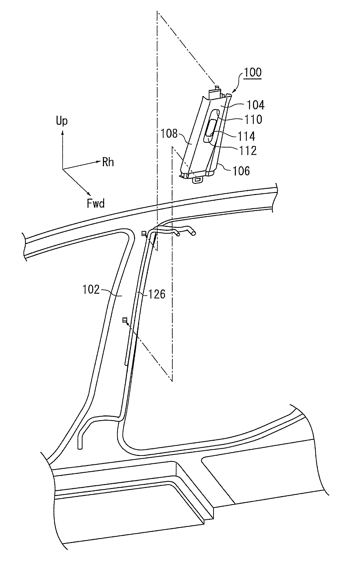
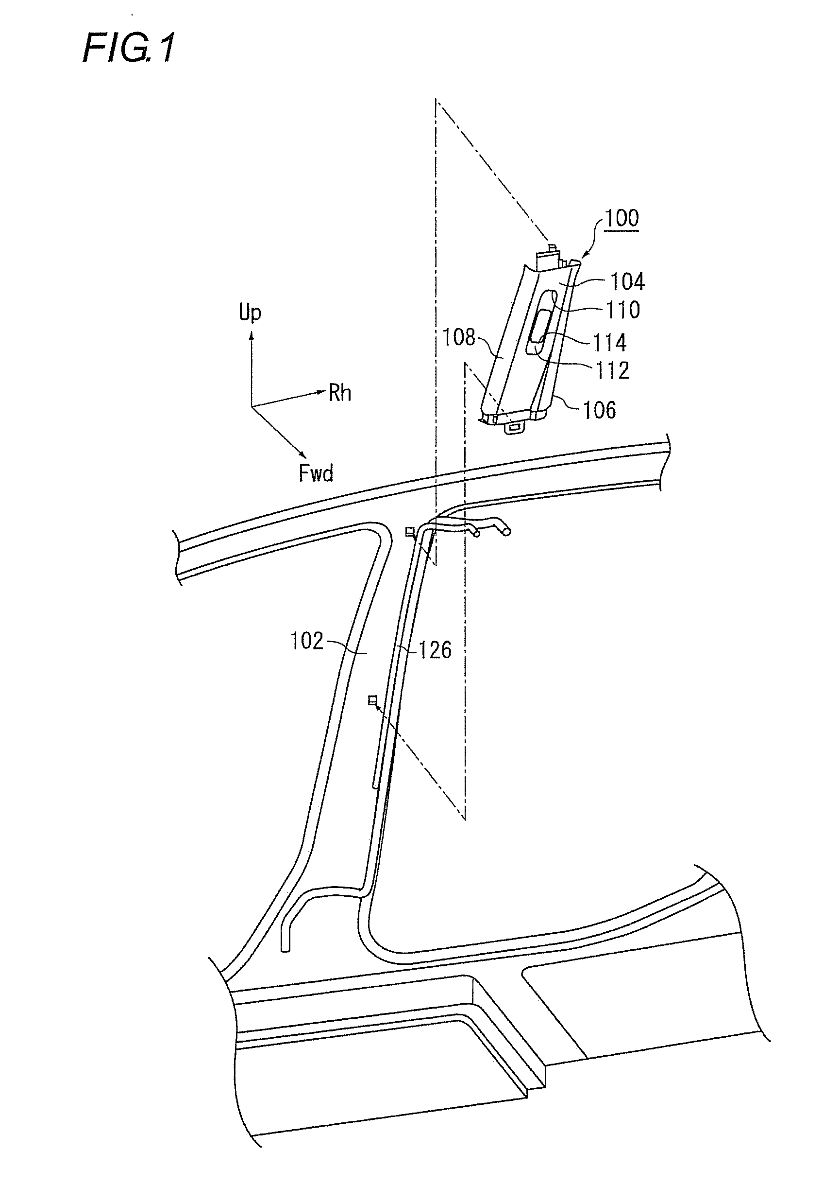
The present invention provides a pillar trim structure that can prevent abnormal noise, caused by rattling of a slider, and avoid layout problems, such as interference between parts, when other parts, such as piping of an air conditioner for a roof, are placed on the backside of the pillar trim. The invention achieves this by cutting out the entrance of a tunnel part widely so that it is more inclined with respect to the pillar trim than the slider, and designing a starting point to prevent interference with other parts. When the slider goes into the entrance of the through-hole, it is supported and inclined with the rib, suppressing rattling and preventing rattling noise. This structure also allows for the interval between the rib and the predetermined starting point to be secured, further strengthening the suppression of rattling.

Problems solved by technology

In the related art, the slider may rattle due to vibrations upon driving and thus collide with an inner surface of the trim, so that an abnormal noise, i.e., rattling noise may be generated.
In this case, a layout problem that the ribs cannot be made to be sufficiently high so as to avoid interference between the parts may occur.
Thus, since it is not possible to sufficiently press the slider towards the other side by the ribs, the slider rattles due to the vibrations upon the driving and thus collides with the inner surface of the trim and the like, so that it is not possible to prevent the abnormal noise, i.e., rattling noise from being generated.

Method used


Image

  • Pillar trim structure
  • Pillar trim structure
  • Pillar trim structure

Examples


Embodiment Construction

[0028]Reference will now be made in detail to the present embodiments of the present invention, examples of which are illustrated in the accompanying drawings, wherein like reference numerals refer to the like elements throughout. The embodiments are described below in order to explain the present invention by referring to the figures.

[0029]Hereinafter, a preferred illustrative embodiment of the present invention will be specifically described with reference to the accompanying drawings. The sizes, materials, other specific numerical values and the like described in the illustrative embodiment are just exemplary so as to easily understand the present invention and do not limit the present invention unless otherwise mentioned. Also, in the specification and the drawings, the constitutional elements having the substantially same functions and configurations are indicated with the same reference numerals and the overlapping descriptions thereof are omitted. Also, the constitutional ele...


PUM


Abstract

There is provided a pillar trim structure. A plate-shaped slider is configured to slide on a backside of a pillar trim in a longitudinal direction. A tunnel part is provided at an upper end of the backside of the pillar trim and formed with a through-hole. A rib is provided so as to stand at one side of an entrance of the through-hole over the longitudinal direction and inclined so that one edge of the slider gets away from the pillar trim as the slider gets over the rib. The entrance is cut out in an elongated shape at an opposite side and is cut out widely so that the entrance is more inclined with respect to the pillar trim than the slider from a predetermined starting point towards the one side and the entrance abuts on the slider at the starting point.

Description

CROSS-REFERENCE TO RELATED APPLICATIONS[0001]This application claims the benefit of Japanese Application No. 2012-119135, filed May 25, 2012, in the Japanese Intellectual Property Office, the disclosure of which is incorporated herein by reference.BACKGROUND OF THE INVENTION[0002]1. Field of the Invention[0003]The present invention relates to a pillar trim structure that is used for a seat belt adjuster adjusting a height of a shoulder anchor of a vehicle.[0004]2. Description of the Related Art[0005]In recent years, a seat belt adjuster has been popularized which adjusts a height of a shoulder anchor, which supports a seat belt restraining a passenger of a vehicle with a shoulder of the passenger, and thus adjusts a path along which the seat belt extends. As disclosed in Patent Document 1, the seat belt adjuster includes a pillar trim and a slider (slide plate). The slider overlaps with a guide hole from a backside of the pillar trim and slides on the backside of the pillar trim in ...

Claims


Application Information

Patent Timeline
IPC IPC(8): B60R13/02
CPCB60R13/025B60R22/201B60R2013/0281B60R2013/0287
Inventor GEMMA, KENTAMATSUMOTO, SHINICHIRO
Owner SUZUKI MOTOR CORP
Learn More