Electric Outboard Motor Transom Clamping System

a technology for electric outboard motors and clamping systems, which is applied in the field of outboard electric motors for boats, can solve the problems of affecting the operation of the boat,

Inactive Publication Date: 2014-01-09
GREZ JOSEPH W
View PDF8 Cites 1 Cited by
  • Summary
  • Abstract
  • Description
  • Claims
  • Application Information

AI Technical Summary

Benefits of technology

The patent describes a propeller hub assembly and electric motor assembly for outboards that are made with durable, lightweight, and inexpensive materials. This makes it more cost-effective than traditional watertight seal systems that use metallic gears and grease. The design allows water to flow into the receiving cavity and act as a lubricant during operation. The entire assembly can be easily removed and replaced if necessary. Additionally, the patent explains an adjustable transom mount that allows the electric motor assembly to be attached to different transoms and rotate freely side-to-side over its longitudinal axis. This mount also enables the entire assembly to rotate forward over the transom, lifting the lower shaft and housing out of the water.

Problems solved by technology

While such propellers are relatively small and inefficient at speeds under 10 mph, the higher RPM and torque requirements of large propellers make them unsuitable for direct drive electric motors.
In addition, because the drive motor units are submerged, leaks around the housing is a failure point.
One drawback with watertight, sealed gear systems is that the gears and bearings must periodically cleaned and re-greased.
Another drawback is that the watertight, sealed system is that the watertight housing can fail allowing water or moisture to enter and damage the gears and bearings.
One drawback with non-watertight gear systems is that water has lower lubricating properties than grease making the gears and bearings vulnerable to greater wear and corrosion.
As a result, the gears and bearings used in non-watertight gear systems must be replaced more often which heretofore has been more expensive and time consuming than lubricating the gears and bearings in watertight, sealed systems.
As a result, the motor's lower shaft and propeller often contact submerged objects or the ground.
Unfortunately, not all small boats have battery straps or buckles or surfaces for affixing a battery.
In addition to holding the battery in a fixed location inside the boat, attaching the batteries to the boat is especially important because small boats can easily overturn in the water causing all non-buoyant objects, such as an electric batteries to be lost.

Method used


Image

  • Electric Outboard Motor Transom Clamping System
  • Electric Outboard Motor Transom Clamping System
  • Electric Outboard Motor Transom Clamping System

Examples


Embodiment Construction

)

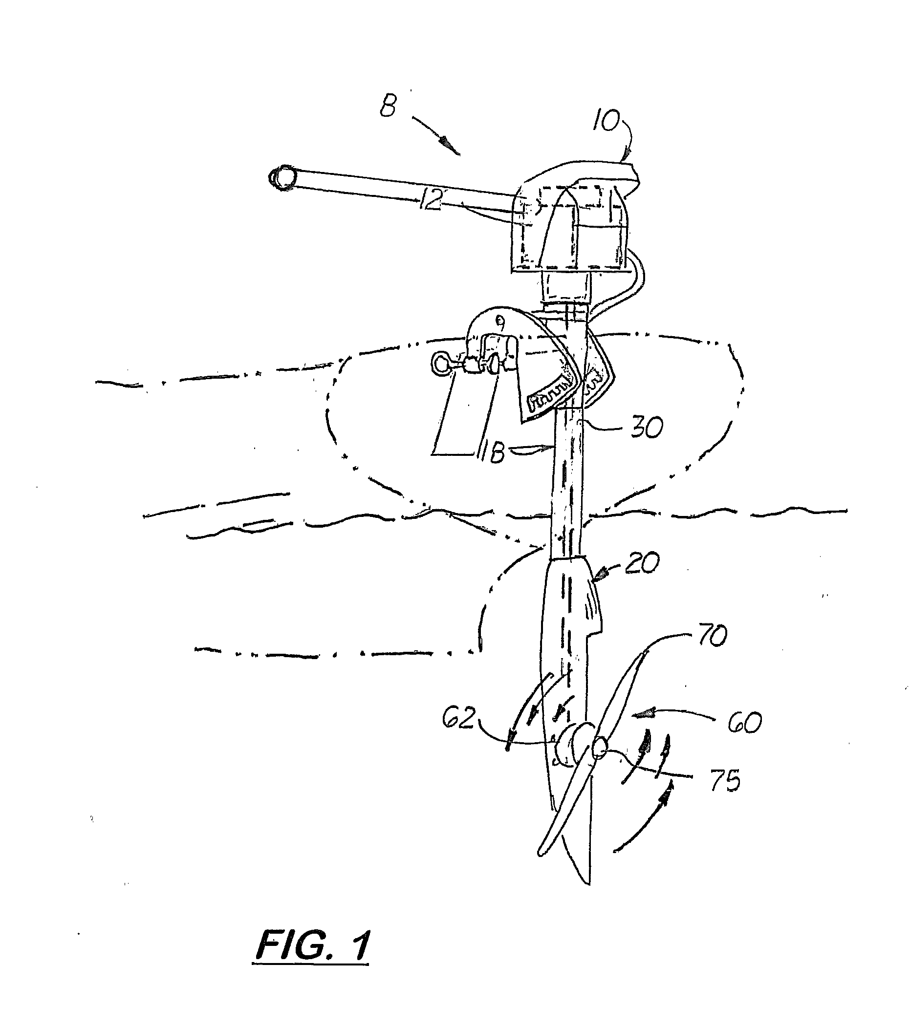
[0041]Referring to the accompanying Figs. there is shown an outboard electric motor assembly generally indicated by the reference number 8. The electric motor assembly 8 includes an electric motor 12 located in an upper housing 10. Attach and extending downward from the upper housing is a lower stem tube 18. Attached or integrally formed on the lower end of the lower stem tube 18 is a lower housing unit 20.

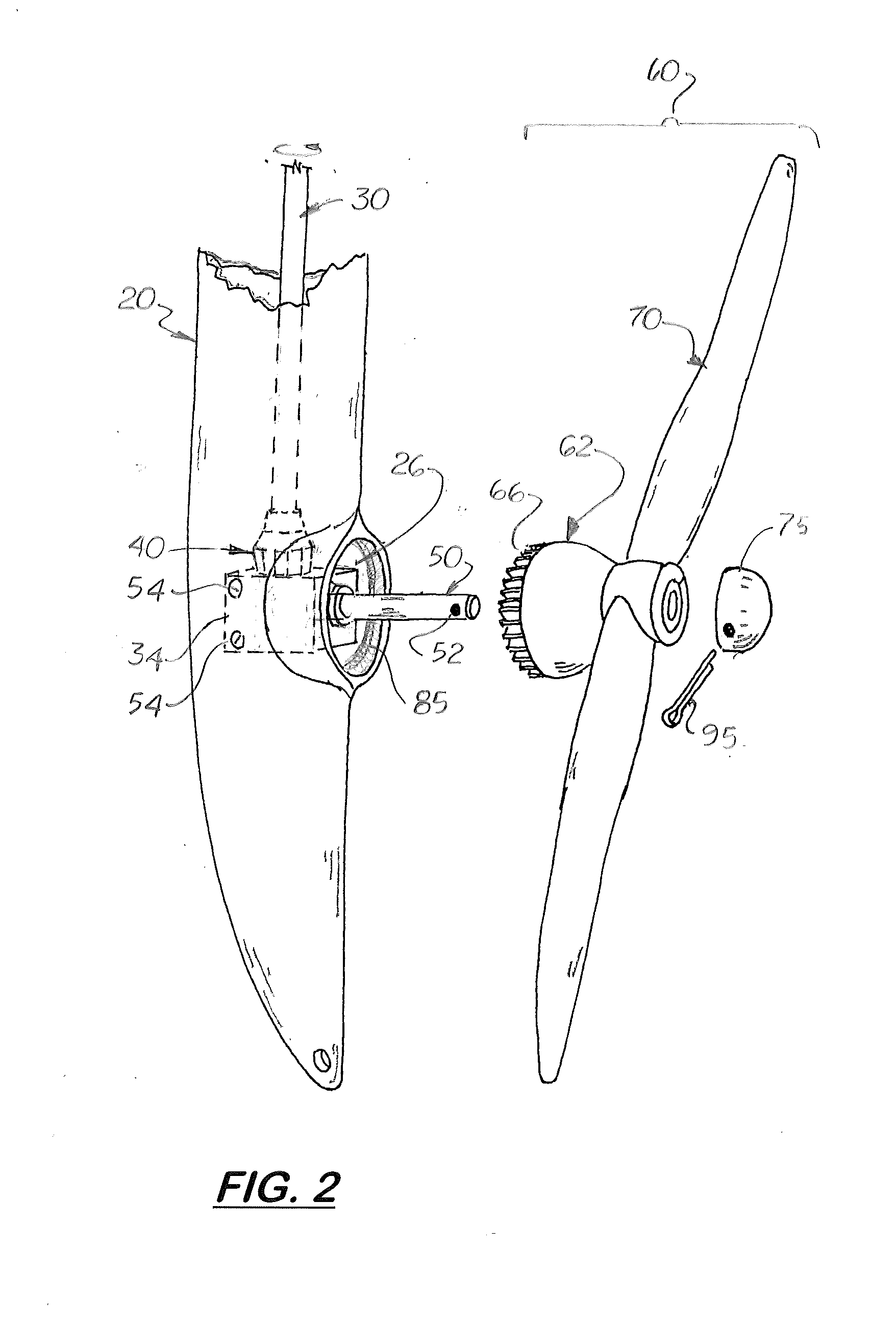
[0042]As shown in FIGS. 2 and 3, formed on the lower housing unit 20 is a receiving cavity 24 with a rearward facing circular opening 26. A drive shaft 30 is coupled at one end to the electric motor and extends downward through the lower stem tube 18 and into the receiving cavity 24. Located inside the receiving cavity 24 is a gear support block 34. The gear support block 34 is fixed inside the receiving cavity 24 and includes an upper bore 36 with a bearing 38 located therein. The distal end of the drive shaft 30 is connected to the bearing 38 thereby enabling it to rotate freel...


PUM


Abstract

An electric outboard motor transom clamping system with two spaced apart side plates pivotally connected by at least one main pivot bolt or pin. Each side plate includes a clamp configured to press against the transom and hold the side plate in a rearward extending fixed position. Each slide plate also includes a ratchet slot located below the main bolt and a plurality of downward oriented pin slots transversely aligned the pins slots on the opposite side plate. Each pin slot is angled upward and rearward between 5 and 25 degrees from the center axis to a line that extends from the bottom of each pin slot to the main pivot bolt. A block member with two longitudinally aligned pins extend into the two ratchet slots. The pins engage the pin slots on the two side plates and hold the block member in fixed position between the two side plates.

Description

[0001]This is a division patent application based on U.S. Utility patent application Ser. No. 13 / 230,810 filed on Sep. 12, 2011 which is based on and claims the filing date benefit of U.S. provisional patent application (Application No. 61 / 381,490) filed on Sep. 10, 2010.COPYRIGHT NOTICE[0002]Notice is hereby given that the following patent document contains original material which is subject to copyright protection. The copyright owner has no objection to the facsimile or digital download reproduction of all or part of the patent document, but otherwise reserves all copyrights whatsoever.BACKGROUND OF THE INVENTION[0003]1. Field of the Invention[0004]This invention relates to outboard electric motors for boats, and more particularly to such outboard electric motors that are lightweight, portable and require little or no maintenance.[0005]2. Description of the Related Art[0006]Operators of oar driven small boats, such as dinghies, canoes, kayaks and inflatable watercraft, find it so...

Claims


Application Information

Patent Timeline
Patent Type & Authority Applications(United States)
IPC IPC(8): B63H20/02B63H21/17
CPCB63H20/02B63H21/17B63H20/08B63H20/14B63H20/007
Inventor GREZ, JOSEPH W.
Owner GREZ JOSEPH W
Why Eureka
Try Eureka