Camshaft assembly and method for producing a camshaft assembly
- Summary
- Abstract
- Description
- Claims
- Application Information
AI Technical Summary
Benefits of technology
Problems solved by technology
Method used
Image
Examples
Embodiment Construction
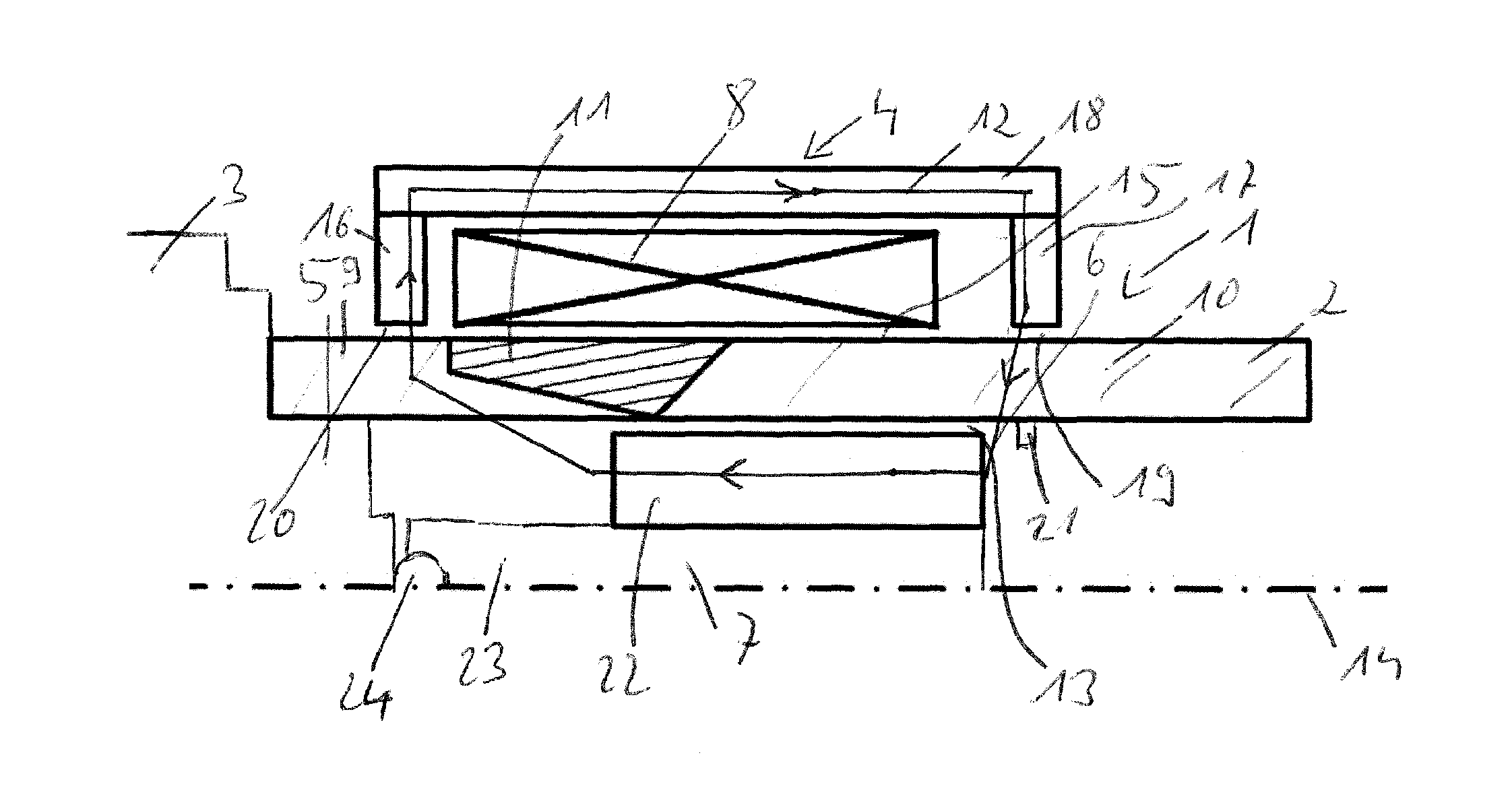
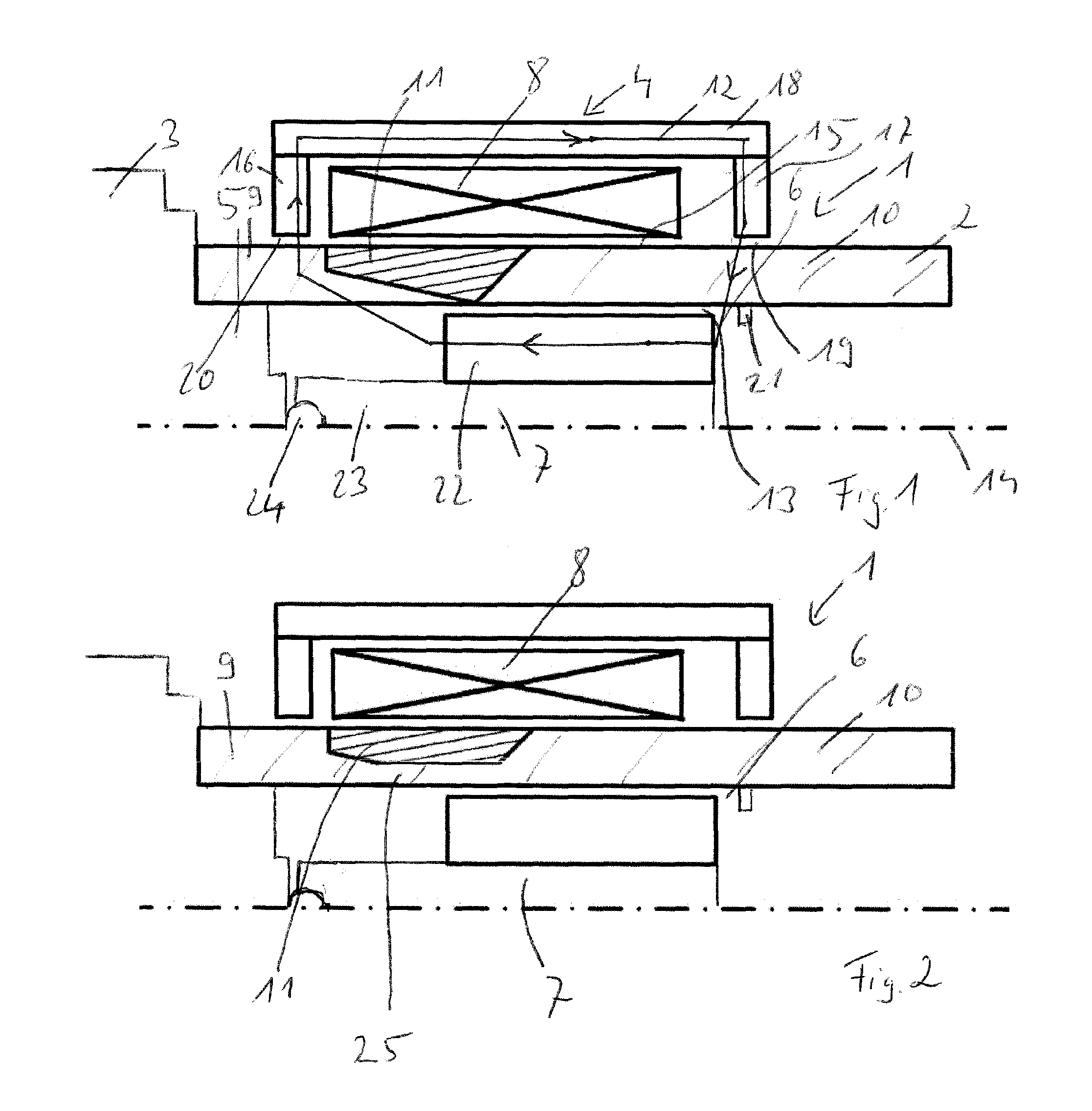
[0038]In FIG. 1 in a diagrammatic longitudinal section view a camshaft assembly is shown having a hollow camshaft of a magnetisable material, steel here, and a hydraulic camshaft adjuster 3, an electromagnetic actuating unit 4 and an actuating partner 5 for the electromagnetic actuating unit in the form of a control valve of the camshaft adjuster 3. The camshaft adjuster 3 together with actuating partner 5 (control valve) is arranged and fixed on the camshaft 2 in a manner known per se. A camshaft adjuster housing, not illustrated separately, is connected directly or indirectly with a crankshaft, likewise not illustrated, of the internal combustion engine, likewise not illustrated and is driven thereby. In addition, the camshaft adjuster 3 has adjustment elements, not shown, connected with the camshaft 2, which adjustment elements can be twisted relative to the camshaft adjuster housing in a manner known per se by a hydraulic actuation. The twisting of these adjustment elements brin...
PUM
| Property | Measurement | Unit |
|---|---|---|
| Magnetic flux | aaaaa | aaaaa |
Abstract
Description
Claims
Application Information
 - R&D
- Intellectual Property
- Life Sciences
- Materials
- Tech Scout
- Unparalleled Data Quality
- Higher Quality Content
- 60% Fewer Hallucinations
Browse by: Latest US Patents, China's latest patents, Technical Efficacy Thesaurus, Application Domain, Technology Topic, Popular Technical Reports.
© 2025 PatSnap. All rights reserved.Legal|Privacy policy|Modern Slavery Act Transparency Statement|Sitemap|About US| Contact US: help@patsnap.com


