
Adjusting device of a hydrostatic module

a technology of hydrostatic module and adjusting device, which is applied in the direction of positive displacement liquid engine, machine/engine, servomotor, etc., can solve the problems of increasing the pivot angle, increasing the imprecision of the position control of the yoke, and increasing the pivot angle. , to achieve the effect of cost-effective and space-saving

Active Publication Date: 2014-01-02
ZF FRIEDRICHSHAFEN AG
View PDF5 Cites 6 Cited by
  • Summary
  • Abstract
  • Description
  • Claims
  • Application Information

AI Technical Summary

Benefits of technology

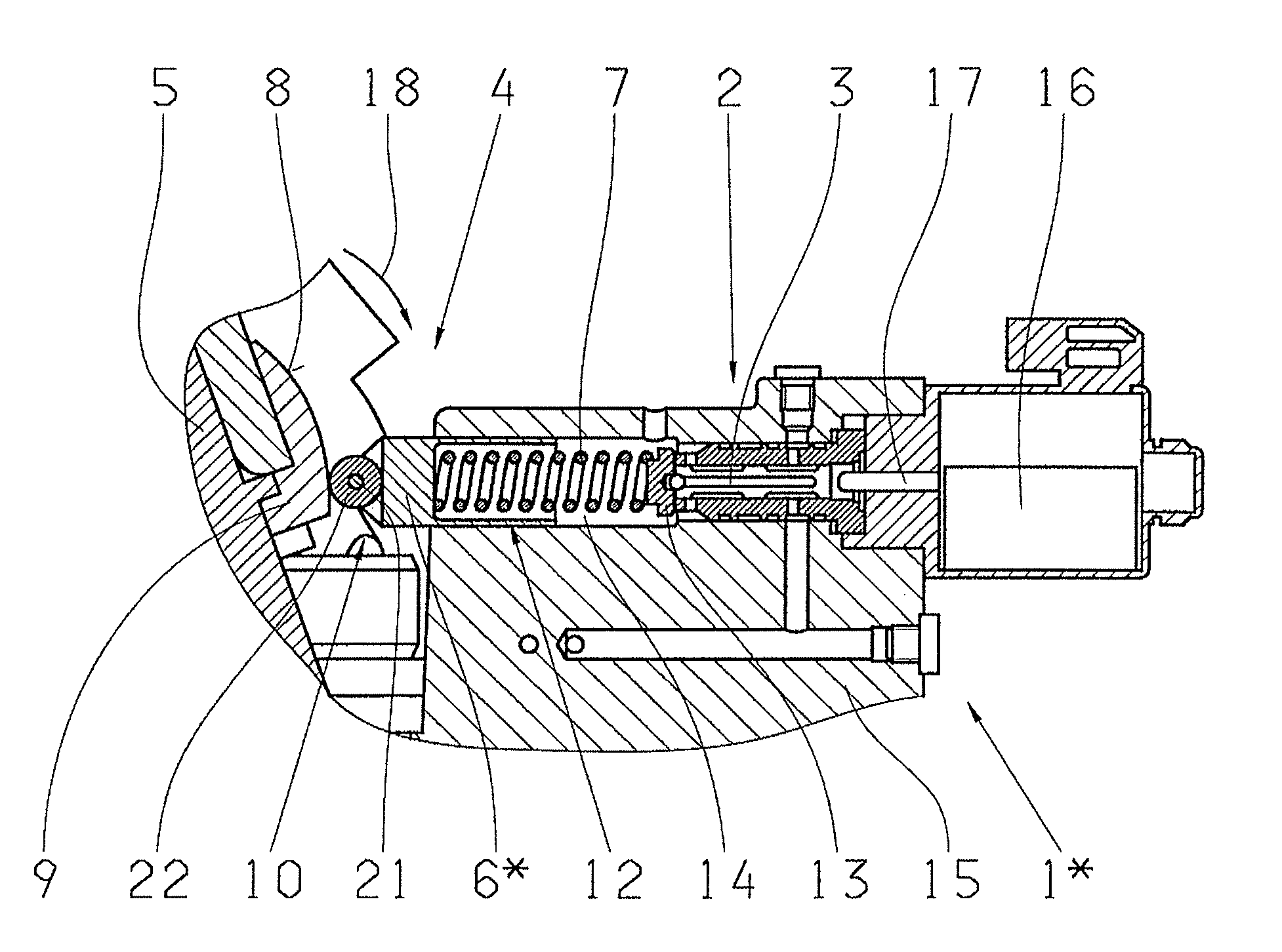
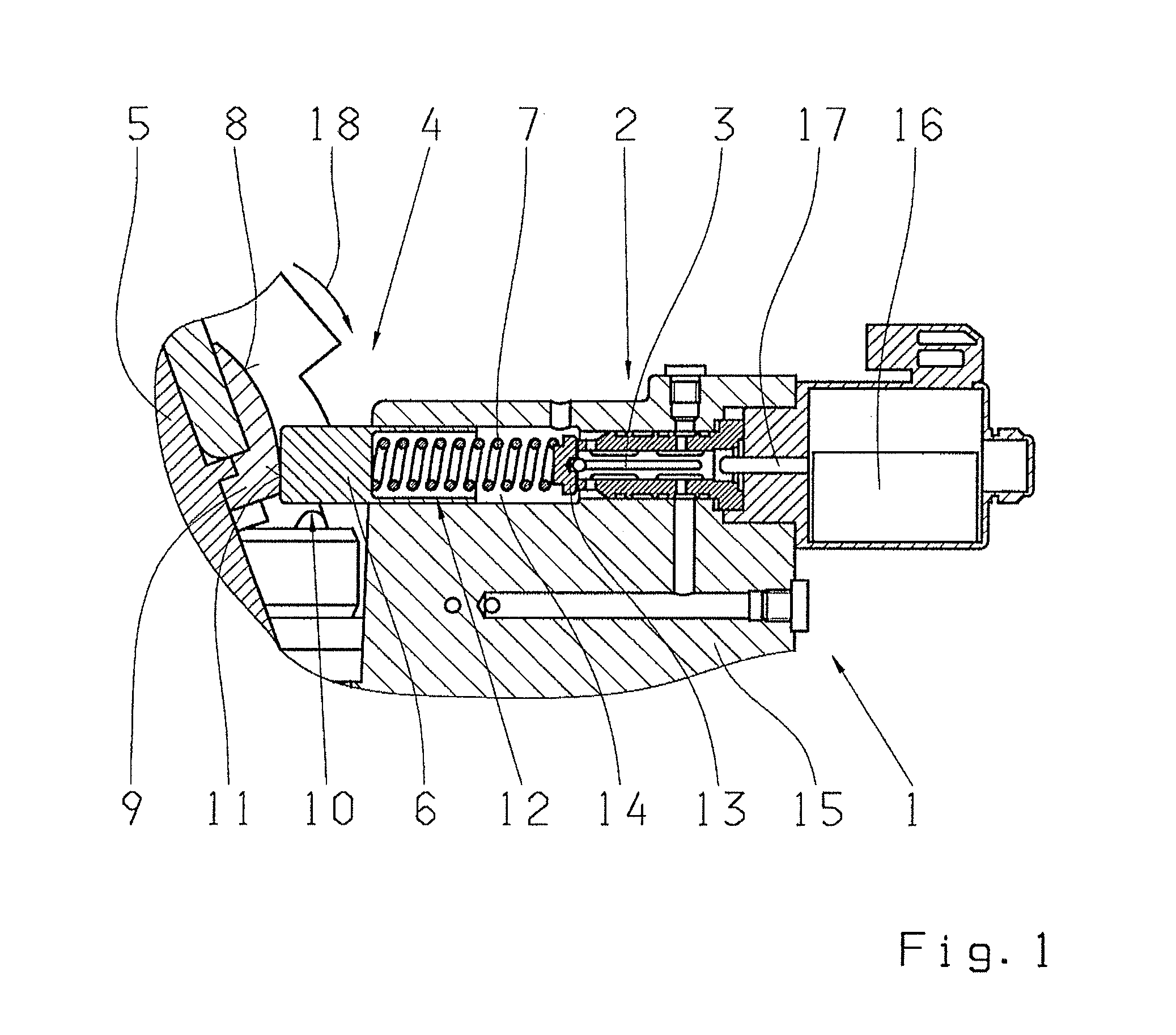
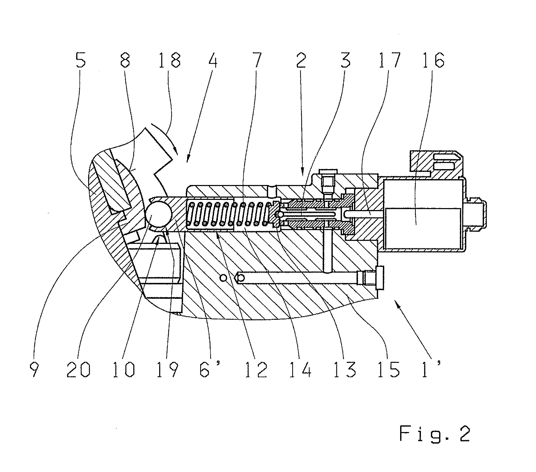
The present invention is proposing an adjusting device for a hydrostatic module that allows for increased precision in position control of the yoke with a simple design. The control arrangement includes a direct, non-positive locking return of the pivoting position of the yoke to the adjusting piston of the position regulating valve, thereby eliminating imprecision in the position control of the yoke caused by the return of the control position of the adjusting cylinder in the known control arrangements. To achieve the lowest possible friction and an especially precise return of the pivoting position of the yoke, it may also provide a sensing piston that is in contact with the feedback surface of the yoke by means of a ball or a roller. The sensing piston, the return spring, and the position regulating valve can be disposed in a stepped bore of a base plate of the hydrostatic module, which is a cost-effective and space-saving solution.

Problems solved by technology

In this way, an unavoidable, existing play in the control connection between the adjusting piston of the adjusting cylinder and the yoke is not registered, which leads to a certain degree of imprecision in the position control of the yoke.
Likewise in this way, the progressive gear ratio of the control connection between the adjusting piston of the adjusting cylinder and the yoke is not registered, which leads to an increased rate of change in the pivot angle of the yoke when there is increased deflection of the adjusting piston, which inevitably leads to an increased imprecision in the position control of the yoke with an increased pivoting angle of the yoke.

Method used


Image

  • Adjusting device of a hydrostatic module
  • Adjusting device of a hydrostatic module
  • Adjusting device of a hydrostatic module

Examples


Embodiment Construction

[0028]FIG. 1 to FIG. 3 each show a control arrangement 1, 1′, 1* according to the invention, which are used to control a hydraulic adjusting cylinder not described in detail here, the control arrangement being disposed radially spaced apart from and tangential with respect to the pivot axis of a yoke 5 of a hydrostatic module, and being operatively connected to the yoke 5 by means of a pivot lever. Through the pivoting of the yoke 5 by the adjusting cylinder, the displacement volume of at least one axial piston machine is adjusted. For a better understanding, it is possible to start with a design of the hydrostatic module as described in DE 10 2008 002 140 A1, for example, which comprises two band axis motors that are hydraulically coupled with one another. The cylinder blocks of these two band axis motors are disposed in the pivotable yoke 5 offset to one another in reference to a common pivot axis. One of the band axis motors functions as a hydrostatic pump, and the other band axi...


PUM


Abstract

An adjusting device of an axial piston machine having a displacement volume that is adjusted by a pivoting yoke. The adjusting device has a cylinder, which is radially spaced from and tangential to the yoke pivot axis. A piston communicates with the yoke and is adjusted by hydraulic pressure change. A control arrangement has a position regulating valve with a control piston which can set the hydraulic pressure acting on the piston. A mechanical return can transfer the yoke pivoting position to the control piston. The valve is axially parallel to the cylinder and radially spaced from the yoke pivot axis. The return comprises an axially movable sensing piston and coaxial return spring which are axially adjacent to the valve. The sensing piston abuts a yoke surface that is eccentric with respect to the pivot axis and connected to the control piston by the return spring.

Description

[0001]This application is a National Stage completion of PCT / EP2012 / 051765 filed Feb. 2, 2012, which claims priority from German patent application serial no. 10 2011 006 102.9 filed Mar. 25, 2011.FIELD OF THE INVENTION[0002]The invention relates to an adjusting device of a hydrostatic module comprising at least one axial piston machine, which can be adjusted in terms of the displacement volume thereof by means of pivoting the yoke, the adjusting device having a hydraulic adjusting cylinder, which is disposed radially spaced apart from and tangential with respect to the pivot axis of the yoke, the hydraulic adjusting cylinder having an adjusting piston, which is operatively connected to the yoke by means of a pivot lever and which can be acted on at two opposing piston surfaces with an adjusting pressure difference of a hydraulic pressure medium, and having a control arrangement, which has a position regulating valve in the form of an electromagnetically controllable hydraulic propo...

Claims


Application Information

Patent Timeline
Patent Type & Authority Applications(United States)
IPC IPC(8): F04B1/29F15B13/04
CPCF04B1/29F15B13/0416F01B3/0032F04B1/328F01B3/10F04B1/32F04B1/10F04B1/20F04B1/2078F15B9/08F16H61/42
Inventor BREHMER, UDOSCHRAFF, BERNDREHTANZ, ROLAND
Owner ZF FRIEDRICHSHAFEN AG
Learn More