
Anti-digging snow-plow bar

Inactive Publication Date: 2014-01-02
LUTKUS BRANDON
View PDF2 Cites 2 Cited by
  • Summary
  • Abstract
  • Description
  • Claims
  • Application Information

AI Technical Summary

Benefits of technology

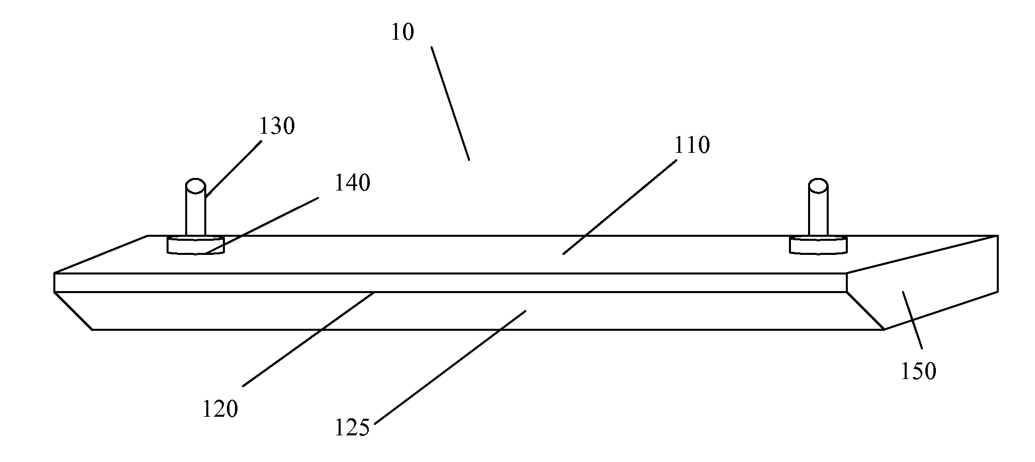
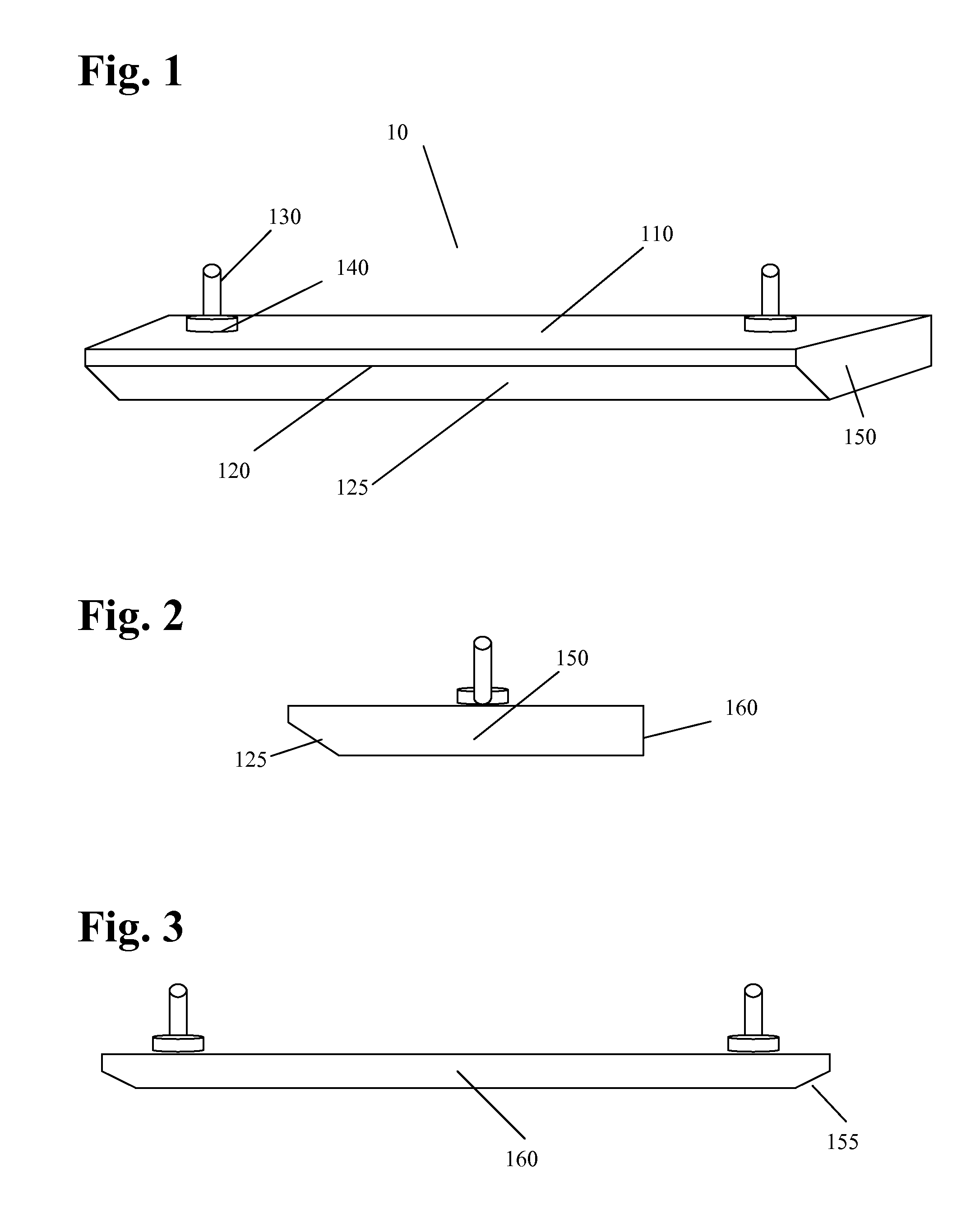
This patent describes a new way to prevent a snow-plow blade from damaging the road surface when plowing soft or unfrozen surfaces like lawns and gravel. It involves using an adjustable plow bar attached to the blade. This bar helps to evenly distribute the weight of the plow and prevents the front edge of the blade from digging into the surface. The bar is made of a hard material like tungsten carbide to ensure durability. Overall, this invention helps to protect the road and provides a safer and effective way to remove snow and other winter weather from soft surfaces.

Problems solved by technology

Since the road surfaces are quite abrasive to provide tire traction, the runners wear relatively rapidly.
These devices are relatively bulky, expensive to manufacture, and difficult to install on the snow plow.
The caster-like wheels frequently jam or flatten and are expensive to maintain and replace.
Further, these devices require regular adjustment, lubrication, and permit debris and the like to lodge or jam between their supporting structure and the moldboard.
One problem in the field of snow plowing not addressed in the prior art, which remains an issue, occurs when plowing over lawns, gravel, soil and soft ground, such as when the temperature rises above freezing and the surface thaws.
Under these conditions, even just the weight of the plow causes the blade to dig into whatever soft surface is under the snow being removed.
The obvious solution is merely to raise the plow a bit, however, this can be difficult on uneven surfaces and results in snow being left behind on the ground.
Although most snow-plows have a pair of skid shoes arranged on either end, which are intended to support the plow blade just above the road surface, this does not solve the problem.
This entails additional cost, time and adversely affects customer relations.
Therefore, unfrozen or soft ground continues to be extremely difficult to plow cleanly, without damaging the surface.
The problem with all of the prior art solutions is the fact the full weight of a very heavy plow is supported only by two relatively small skid plates.

Method used


Image

  • Anti-digging snow-plow bar
  • Anti-digging snow-plow bar

Examples


Embodiment Construction

[0019]The following description relates to certain preferred embodiments of an apparatus and method for preventing a snow-plow blade from damaging the road surface, when plowing lawns, gravel, soil and other soft or unfrozen surfaces. Numerous variations and modifications, other than those specifically indicated herein, will be readily apparent to those of sufficient skill in the art. In addition, certain terms are used throughout the discussion in order to provide a convenient frame of reference with regard to the accompanying drawings, such as “top”, “bottom”, and the like. However, such terms are not intended to be specifically limiting of the invention, except where so indicated in the claims.

[0020]The invention provides novel technology for preventing a snow-plow blade from damaging the road surface, when plowing lawns, gravel, soil and other soft or unfrozen surfaces, overcoming the disadvantages of the available technology currently used. The equipment is simple, inexpensive ...


PUM


Abstract

An adjustable plow bar for a snow-plow blade, which is fastened to the plow blade to reduce digging into soft road surfaces, includes a bar having two side edges and a front edge substantially equal in length to the length of the plow blade, and mounting posts attached to the upper surface of the bar for mounting the bar to the plow and for adjusting the bar relative to the plow blade. The length of the bar distributes the weight of the plow evenly along length of the blade, and the front edge of the bar is beveled on the underside, which prevents the front edge from digging. Preferably the side edges of the bar also are beveled on the underside thereof, and the composition of the bar includes an abrasion-resistant material, such as tungsten carbide and other hard carbides.

Description

BACKGROUND OF THE INVENTION[0001]1. Field of the Invention[0002]The invention pertains to the field of excavation or snow removal. More particularly, the invention pertains to a plow bar for a snow-plow blade, which is fastened to the plow blade to reduce digging into soft road surfaces.[0003]2. Description of the Related Art[0004]The concept of snow plow runners or skid plates to hold a snow-plow blade a predetermined distance from the roadway is old in the art. One type of commonly used snow-plow runner includes of a pair of wear plates composed of a high abrasion-resistant steel or iron mounted at each end of the plow. The purpose of the wear plates is to make contact with the abrading surface of the roadway and hold the snow-plow blade off the roadway as the blade passes over the roadway, which typically is asphalt or concrete. Since the road surfaces are quite abrasive to provide tire traction, the runners wear relatively rapidly. To prevent undue wear on the blade, typically t...

Claims


Application Information

Patent Timeline
IPC IPC(8): E01H5/06
CPCE01H5/065
Inventor LUTKUS, BRANDON
Owner LUTKUS BRANDON
Learn More