Method and device for creating computational models for nonlinear models of position encoders

Inactive Publication Date: 2013-12-26
ROBERT BOSCH GMBH
View PDF1 Cites 2 Cited by
  • Summary
  • Abstract
  • Description
  • Claims
  • Application Information

AI Technical Summary

Benefits of technology

The patent suggests a method for solving differential equation models of physical systems by dividing them into a linear and nonlinear part. This allows for the use of non-simplified models, reducing the risk of oscillations and inaccuracies. The method also allows for discretization of physical models without simplification and implementation in control units with limited computing capacity. The technical effect is improved accuracy and efficiency in the analysis and control of physical systems.

Problems solved by technology

Despite the use of simplified functions for mapping friction or the like, these differential equation systems are not linear.
In addition, a special challenge is unsteadiness such as that in nonlinear spring characteristic lines of return springs or the like, for example, i.e., return springs having different characteristics in different areas; so far it has been possible only with great difficulty to map such unsteadiness in the underlying differential equation system.
This discretization often results in equations systems that cannot be solved mathematically and therefore must be solved iteratively, i.e., usually in a very time-consuming procedure.
This is often impractical for use in real time since control units for internal combustion engines, for example, have only a limited computing capacity.
Another requirement of the computational model which maps the physical system is adequate precision, since otherwise undesirable effects such as vibrations during regulations or misdiagnoses may occur when using the computational model for diagnostic purposes.
Nonlinear equations describing a physical system often cannot be discretized in a stable manner using conventional explicit discretization methods.

Method used


Image

  • Method and device for creating computational models for nonlinear models of position encoders
  • Method and device for creating computational models for nonlinear models of position encoders
  • Method and device for creating computational models for nonlinear models of position encoders

Examples


Embodiment Construction

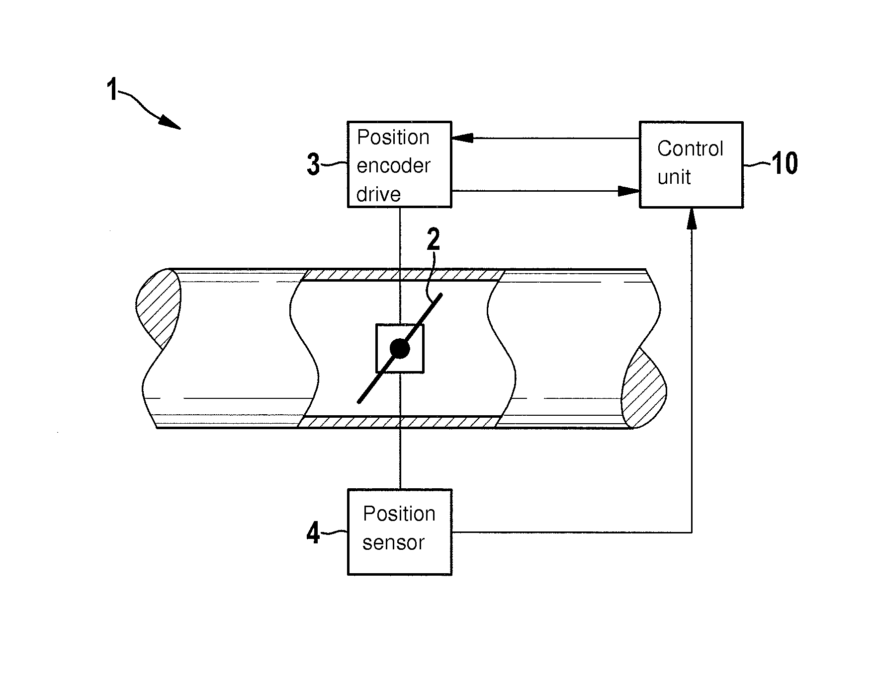
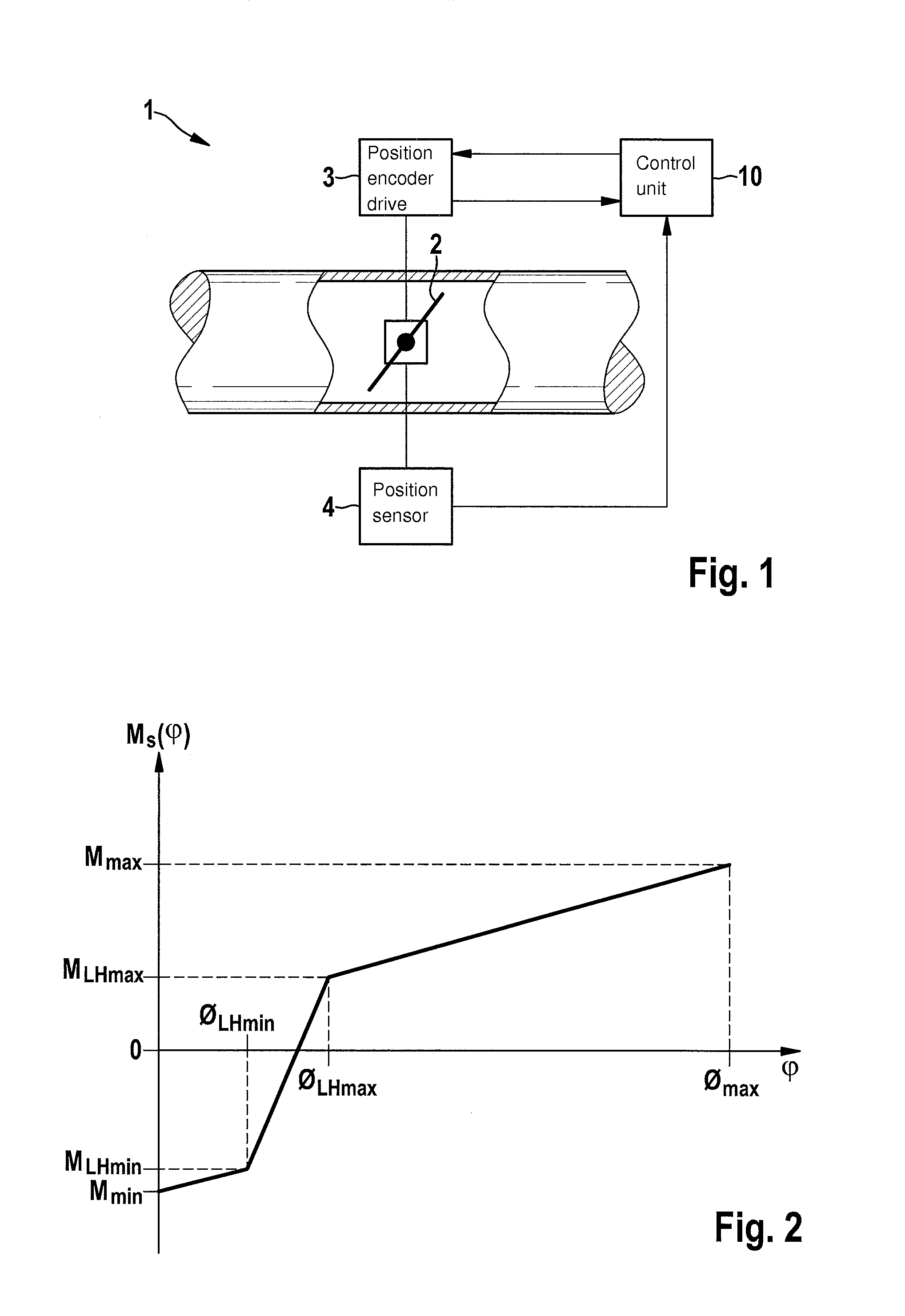
[0036]FIG. 1 shows a position encoder system 1 for adjusting the position of an actuator 2. This method for creating a computational model which maps the physical model of position encoder system 1 as accurately as possible and makes it suitable for use in a control unit having a limited computing capacity, for example, is described below on the basis of a throttle valve position encoder, which is able to adjust a throttle valve as actuator 2. However, it is also possible to apply the method described below to other position encoder systems whose physical behavior is describable by nonlinear differential equations.

[0037]Actuator 2 is moved with the aid of a position encoder drive 3. Position encoder drive 3 may be designed as an electromechanical actuator, which may be designed, for example, as a dc motor, as an electronically commutated motor or as a stepping motor. With the aid of a position sensor 4, the position actually assumed by actuator 2 may be detected and analyzed.

[0038]P...


PUM


Abstract

A method is described for ascertaining a computational model for a position encoder system, in particular for a position encoder for controlling a gas mass flow rate for an internal combustion engine, having the following steps: providing a differential equation system with at least one nonlinear term; dividing the differential equation system to obtain a linear part which is describable by a linear differential equation and a nonlinear part which is describable by a nonlinear differential equation; discretizing the linear part of the differential equation system with the aid of a first discretization method to obtain a computational model for the discretized linear part; discretizing the nonlinear part of the differential equation system with the aid of a second discretization method to obtain a computational model for the discretized nonlinear part; combining the computational models of the discretized linear part and the discretized nonlinear part of the differential equation system to obtain the computational model for the position encoder system.

Description

FIELD OF THE INVENTION[0001]The present invention relates to methods for creating a computational model for a physical system, in particular for a position encoder for controlling a gas mass flow rate in an engine system.BACKGROUND INFORMATION[0002]For designing controllers for regulating mechatronic actuator systems, such as, for example, position encoders for throttle valves in internal combustion engines and for their computational simulation, differential equation systems are usually created to map their physical behavior. Despite the use of simplified functions for mapping friction or the like, these differential equation systems are not linear.[0003]In addition, a special challenge is unsteadiness such as that in nonlinear spring characteristic lines of return springs or the like, for example, i.e., return springs having different characteristics in different areas; so far it has been possible only with great difficulty to map such unsteadiness in the underlying differential e...

Claims


Application Information

Patent Timeline
IPC IPC(8): G06F17/50
CPCG06F17/5009G06F30/20G06F2111/10
Inventor WAGNER, ALEXANDREBUEHRLE, RALF
Owner ROBERT BOSCH GMBH
Why Eureka
Try Eureka