Switched Reluctance Motor and Switched Reluctance Motor Drive System

a technology of switched reluctance and motor, which is applied in the direction of dynamo-electric machines, instruments, master clocks, etc., can solve the problems of induction motor, weight and efficiency, and efficiency further reduced, and achieve the effect of reducing torque ripple and vibration of switched reluctance motors

Inactive Publication Date: 2013-12-26
MOTOR SYST
View PDF5 Cites 4 Cited by
  • Summary
  • Abstract
  • Description
  • Claims
  • Application Information

AI Technical Summary

Benefits of technology

[0017]Further preferably, the width of each of the salient poles of each of the plurality of rotor units in the direction of rotation is set to be larger than the width of each of the magnetic poles of the corresponding each of the stator units. This width relationship of each salient pole and each corresponding magnetic pole reduces a period of time during which each salient pole is prevented from facing the magnetic poles of the corresponding stator unit, thereby reducing a period of time during which the attractive force exerted by each magnetic pole on the salient poles of the corresponding rotor unit is reduced, so that the torque ripple and vibration of the switched reluctance motor can be reduced.

Problems solved by technology

However, in recent years, the importance of reduction in CO2 emissions and rare earth resource has been recognized, so that the use of the conventional electric motor drive systems, as they are, causes the following problems.
On the other hand, induction motors have disadvantages in weight and efficiency, in which the efficiency is further reduced by high frequency components of pseudo sine wave generated by a PWM inverter.
Conventional reluctance motors have problems of low efficiency, high weight and difficulty in regenerative braking as well as large torque ripple, vibration and noise.
These problems are due to the inherently high reluctance of the coils of the reluctance motors, which causes difficulty in quickly controlling current, which in turn causes difficulty in supplying each coil with a current having an advantageous waveform in view of torque variations.
Further, while in the excitation coil a primary current to generate attractive force is superimposed on a regenerative current when regenerative braking, it is difficult to control to effectively separate and recover the regenerative current to a power supply.
In addition, the attractive force exerts inward force on an outer frame, which causes vibration and noise.

Method used


Image

  • Switched Reluctance Motor and Switched Reluctance Motor Drive System
  • Switched Reluctance Motor and Switched Reluctance Motor Drive System
  • Switched Reluctance Motor and Switched Reluctance Motor Drive System

Examples


Embodiment Construction

[0045]Embodiments of the present invention, as best mode for carrying out the invention, will be described hereinafter with reference to the drawings. It is to be understood that the embodiments described herein are not intended as limiting, or encompassing the entire scope of, the present invention. Note that like parts are designated by like reference numerals, characters or symbols throughout the drawings.

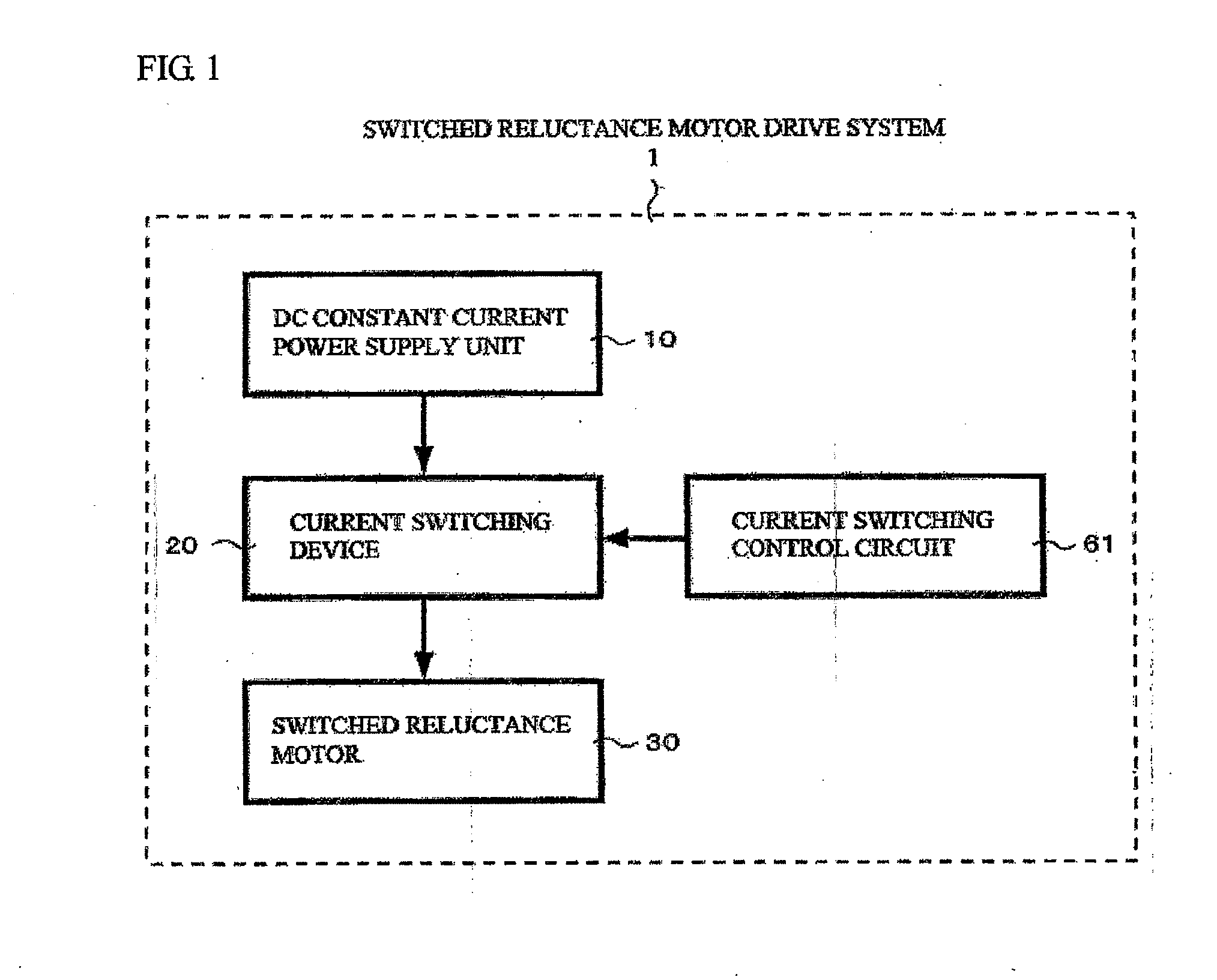
[0046]FIG. 1 is a schematic block diagram showing a basic structure of a switched reluctance motor drive system 1 according to an embodiment of the present invention. Referring to FIG. 1, the switched reluctance motor drive system 1 comprises a DC (direct current) constant current power supply unit 10, a current switching device 20, a switched reluctance motor 30, and a current switching control circuit (flip-flop control circuit) 61 (refer to FIG. 6). The DC constant current power supply unit 10 outputs a DC current having a value corresponding to a command from a control syste...


PUM


Abstract

A regenerative switched reluctance motor and a motor drive system therefor are provided. The motor has a rotor 33 with stacked rotor units 33a-33d each comprising 2n salient poles and a stator 31 with stacked stator units 31a-31d surrounded by and corresponding to the rotor units and each comprising 4n magnetic poles to form a predetermined gap with the salient poles of the corresponding rotor unit. A first excitation coil 32(A) is wound on every other one of the 4n magnetic poles of each stator unit, while a second excitation coil 32(B) is wound on the remaining magnetic poles thereof. The rotor units are sequentially shifted by a predetermined angle in angular position relative to the stator units. The switched reluctance motor and the motor drive system can efficiently drive the motor and recover regenerative power with little torque ripple and noise.

Description

BACKGROUND OF THE INVENTION[0001]1. Field of the Invention[0002]The present invention relates to a switched reluctance motor comprising a rotor having a plurality of salient poles and a stator which is arranged inside the rotor and has salient portions with excitation coils wound thereon to form a plurality of magnetic poles, and also relates to a switched reluctance motor drive system for sequentially supplying current to the excitation coils so as to rotate the rotor arranged outside the stator.[0003]2. Description of the Related Art[0004]Conventionally, in widely known electric motor drive systems, there are (1) those comprising a PWM (Pulse Width Modulation) inverter and a three-phase synchronous motor, and (2) those comprising a PWM inverter and a three-phase induction motor. They were proposed in the 1960s and 1970s, and have been widely used in elevators, street cars, cranes, air conditioners, electric cars, hybrid cars and so on as power electronics and electronic circuit te...

Claims


Application Information

Patent Timeline
Patent Type & Authority Applications(United States)
IPC IPC(8): H02K19/10
CPCH02K19/103H02K29/03
Inventor UMEMORI, TAKASHITANAKA, MAKOTO
Owner MOTOR SYST
Why Eureka
Try Eureka