System for generating electrical power

a technology of electrical power generation and electrical power, applied in the direction of electric generator control, machines/engines, sustainable buildings, etc., can solve the problems of wasting energy, aircraft exhausting a lot of wind, and regular wind turbines cannot be used to collect aircraft generated wind

Active Publication Date: 2013-12-26
YUDKOVITZ ALEXANDER JAY +4
View PDF12 Cites 4 Cited by
  • Summary
  • Abstract
  • Description
  • Claims
  • Application Information

AI Technical Summary

Benefits of technology

The present invention relates to a system that can generate electricity from the exhaust wind of an aircraft when it takes off. This system includes multiple blades that rotate on a shaft with bearings at each end. A generator is also connected to the shaft. There are two ways to attach the system to a platform: one way involves securing the attachment points to a blast pad on a runway threshold, while the other method involves attaching them to a building or structure near the runway. Overall, this technology allows for efficient use of waste energy and provides a sustainable source of clean energy.

Problems solved by technology

The patent text describes a system that aims to convert wind created by aircraft exhaust into electrical power. The technical problem that the invention addresses is the wasting of energy during takeoff, as conventional blast fences do not collect any energy from the wind. Additionally, regular wind turbines cannot be used because they would interfere with air traffic. Therefore, there is a need for a system that can efficiently convert the wind created by aircraft exhaust into electrical power.

Method used


Image

  • System for generating electrical power
  • System for generating electrical power

Examples


Embodiment Construction

[0012]The following detailed description is of the best currently contemplated modes of carrying out exemplary embodiments of the invention. The description is not to be taken in a limiting sense, but is made merely for the purpose of illustrating the general principles of the invention, since the scope of the invention is best defined by the appended claims.

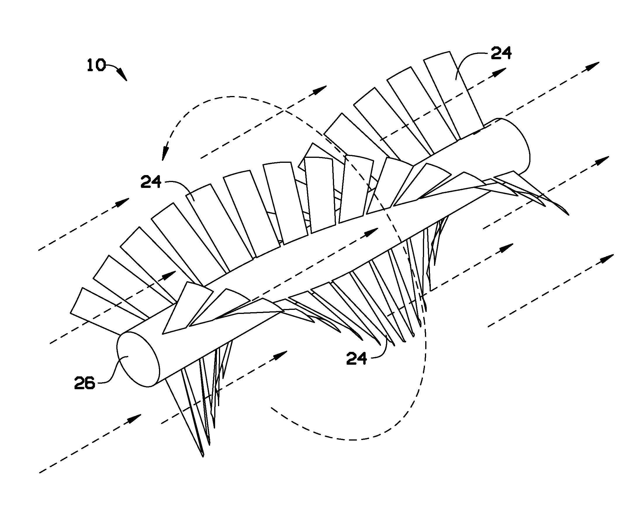
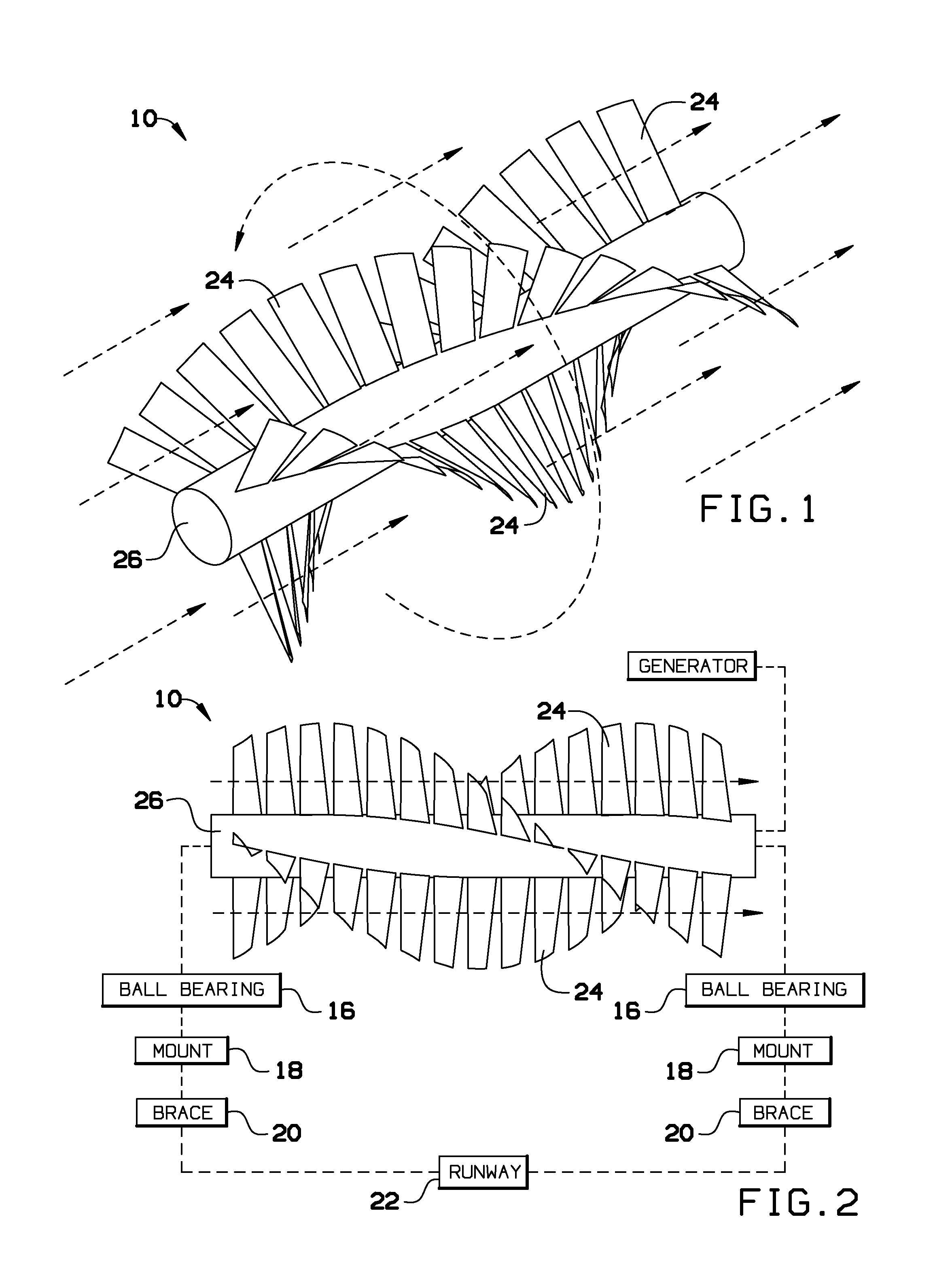
[0013]Broadly, an embodiment of the present invention provides a system that works to convert wind created by aircraft exhaust into electrical power. The system uses a modified version of an Archimedes screw-shaped wind turbine placed behind a runway to collect the energy, currently wasted, from the aircraft and convert it to usable electricity.

[0014]Referring now to FIGS. 1 and 2, a system 10 for generating electrical power according to an exemplary embodiment of the present invention may include a plurality of rotatably supported blades 24 disposed about a shaft 26. Each blade 24 may have a geometrical shape, for example, a re...


PUM


Abstract

An energy generation system works to convert wind created by aircraft exhaust into electrical power. The system uses a modified version of an Archimedes screw-shaped wind turbine placed behind a runway to collect the energy, currently wasted, from the aircraft and convert it to usable electricity.

Description


Claims


Application Information

Patent Timeline
Owner YUDKOVITZ ALEXANDER JAY
Why Eureka
Try Eureka