
Sensor substrate and sensing display panel having the same

a technology of display panel and substrate, applied in optics, instruments, transistors, etc., can solve the problems of low power consumption, deficiency of viewing angle of liquid crystal layers, and relatively thin and light weight of liquid crystal display apparatuses

Active Publication Date: 2013-12-26
SAMSUNG DISPLAY CO LTD
View PDF5 Cites 156 Cited by
  • Summary
  • Abstract
  • Description
  • Claims
  • Application Information

AI Technical Summary

Benefits of technology

The patent text describes a sensor substrate that prevents static electricity from causing negative effects on display panels. The sensor substrate includes electrodes made of metal, which protects the display from static electricity buildup and discharge. A bias signal, such as a direct current voltage, is applied to the electrodes to improve the static electricity blocking effect. This results in a safer and more reliable display panel for use in various applications.

Problems solved by technology

A liquid crystal display (LCD) apparatus typically relatively thin and light weight, as well as consumes low levels of power.
These liquid crystal layers, however, can be deficient with respect to viewing angles.
It is noted, however, that LCD panels utilizing horizontal electric fields including an opposing substrate opposite to the array substrate and not including a common electrode can be prone to negative effects associated with static electricity, such as static electricity build-up and discharge.

Method used


Image

  • Sensor substrate and sensing display panel having the same
  • Sensor substrate and sensing display panel having the same
  • Sensor substrate and sensing display panel having the same

Examples


Embodiment Construction

[0045]In the following description, for the purposes of explanation, numerous specific details are set forth in order to provide a thorough understanding of various exemplary embodiments. It is apparent, however, that various exemplary embodiments may be practiced without these specific details or with one or more equivalent arrangements. In other instances, well-known structures and devices are shown in block diagram form in order to avoid unnecessarily obscuring various exemplary embodiments.

[0046]In the accompanying figures, the size and relative sizes of layers and / or regions may be exaggerated for clarity and descriptive purposes. Also, like reference numerals denote like elements.

[0047]When an element or layer is referred to as being “on,”“connected to,” or “coupled to” another element or layer, it may be directly on, directly connected to, or directly coupled to the other element or layer, or intervening elements or layers may be present. When, however, an element is referred...


PUM


Abstract

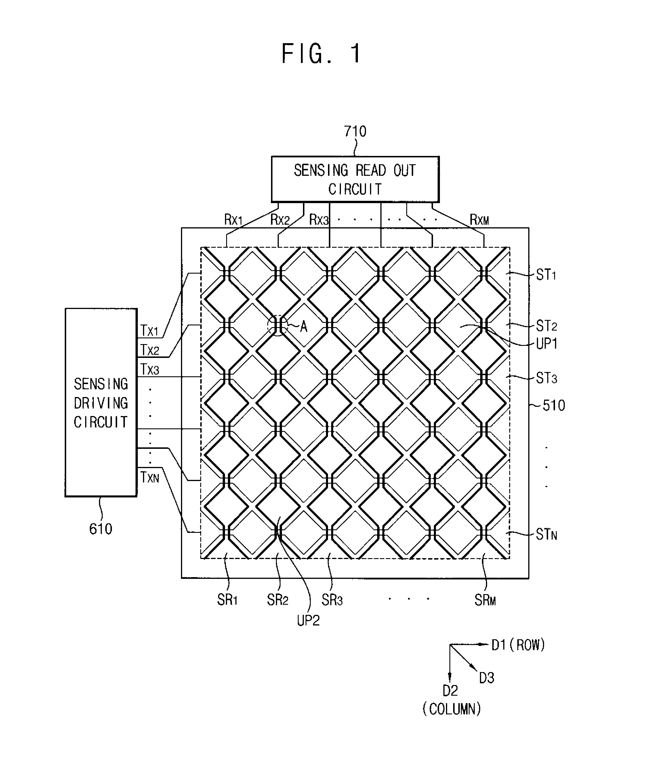
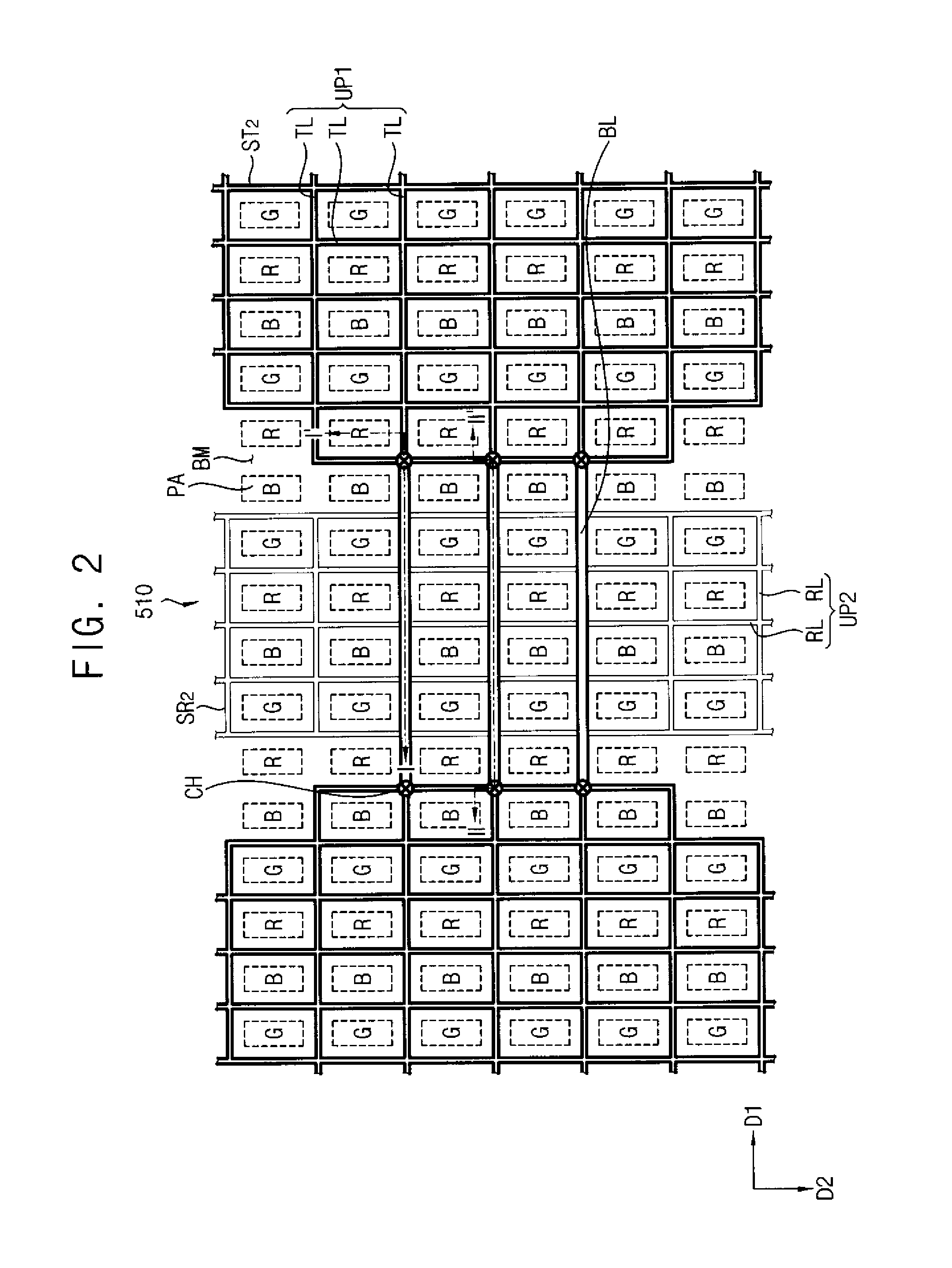
A sensor substrate includes a base substrate, a black matrix pattern, a sensing electrode pattern, a driving electrode pattern, and at least one bridge line. The black matrix pattern is disposed on the base substrate and divides the base substrate into a light transmission area and a light blocking area. The sensing electrode pattern includes a plurality of first unit patterns arranged in association with a first direction. The driving electrode pattern includes a plurality of second unit patterns arranged in association with a second direction and disposed adjacent to the plurality of first unit patterns. The at least one bridge line is connected between at least two of the plurality of first unit patterns or between at least two of the plurality of second unit patterns.

Description

CROSS-REFERENCE TO RELATED APPLICATION[0001]This application claims priority from and the benefit of Korean Patent Application No. 10-2012-0066942, filed on Jun. 21, 2012, which is incorporated by reference for all purposes as if set forth herein.BACKGROUND[0002]1. Field[0003]Exemplary embodiments of the present disclosure relate to sensor substrates and sensing display panels incorporating the sensor substrate, and more particularly to sensor substrates and sensing display panels incorporating sensor substrates to prevent damage associated with static electricity.[0004]2. Discussion[0005]A liquid crystal display (LCD) apparatus typically relatively thin and light weight, as well as consumes low levels of power. As such, LCDs are generally used in association with monitors, laptop computers, cellular phones, personal digital assistants, and the like. Conventional LCDs include an LCD panel configured to display images via light transmittance through liquid crystal, the light radiatin...

Claims


Application Information

Patent Timeline
IPC IPC(8): H01L31/0232H01L31/12
CPCH01L31/0232H01L31/12G02F1/13338G06F3/0412G06F2203/04112G06F3/0443G06F3/0446H01L27/14623G02F1/133G02F1/1343G02F1/136204G06F3/0445H01L27/027H01L27/1214
Inventor KIM, IN-CHEOLPARK, JI-HONGLEE, HYUN-JULEE, IL-HOCHOI, MOON-SUNGHWANG, SEONG-MOKIM, KI-HYUKNAM, SEUNG-HO
Owner SAMSUNG DISPLAY CO LTD
Learn More