
Self-adhesive tet coil holder with alignment feature

Active Publication Date: 2013-12-12
HEARTWARE INC
View PDF2 Cites 62 Cited by
  • Summary
  • Abstract
  • Description
  • Claims
  • Application Information

AI Technical Summary

Benefits of technology

The invention described in this patent text has specific technical effects that are important for understanding its context and logic. The technical effects of the patent text will be revealed through the detailed description provided below.

Problems solved by technology

However, such a wire poses a risk of infection, particularly when left in place for months or years.
Measures to alleviate this risk add to the burden placed upon the patient and caregivers.
Poor alignment will result in poor energy transmission from the external coil to the internal coil.

Method used


Image

  • Self-adhesive tet coil holder with alignment feature
  • Self-adhesive tet coil holder with alignment feature
  • Self-adhesive tet coil holder with alignment feature

Examples


Embodiment Construction

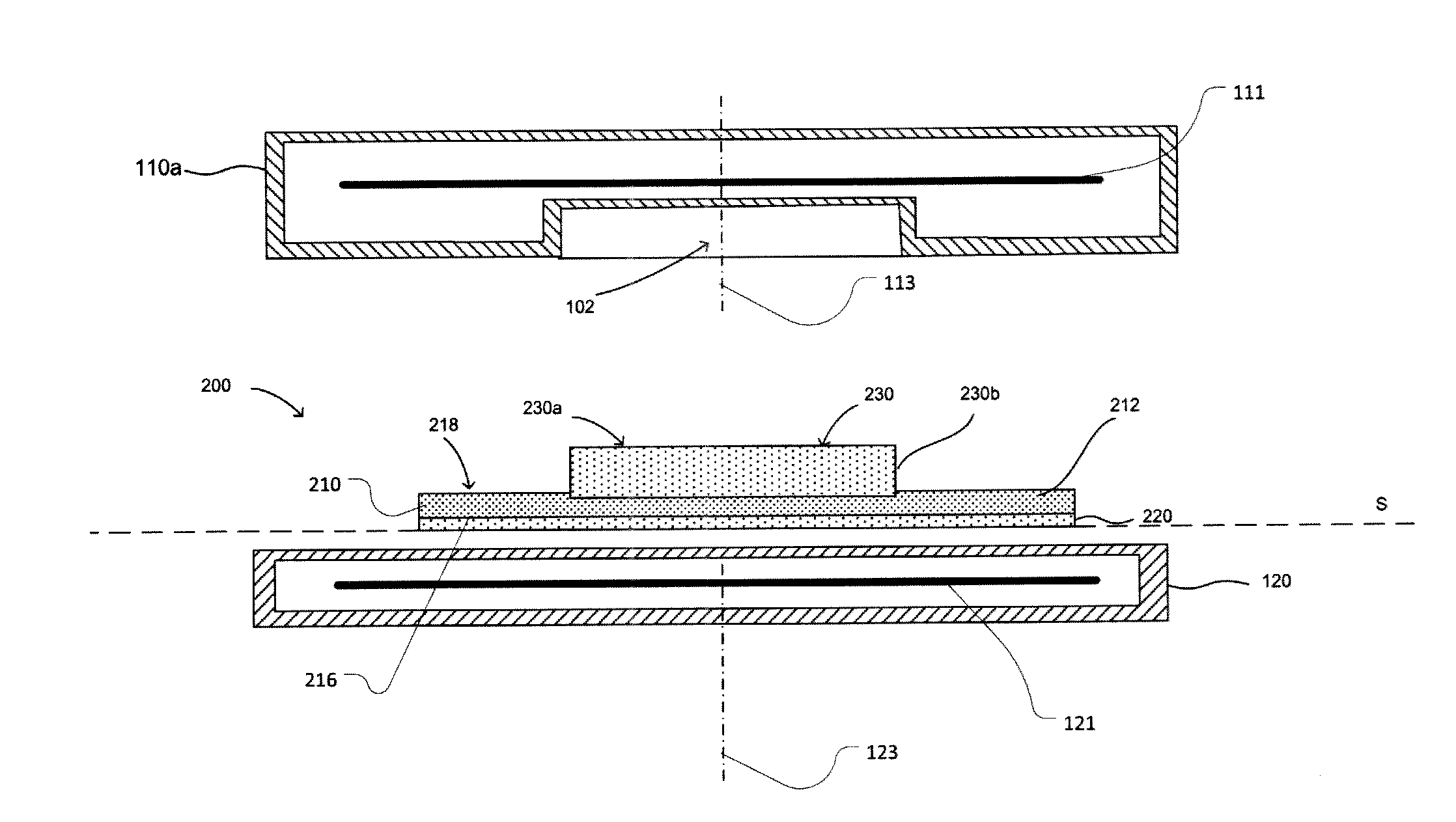
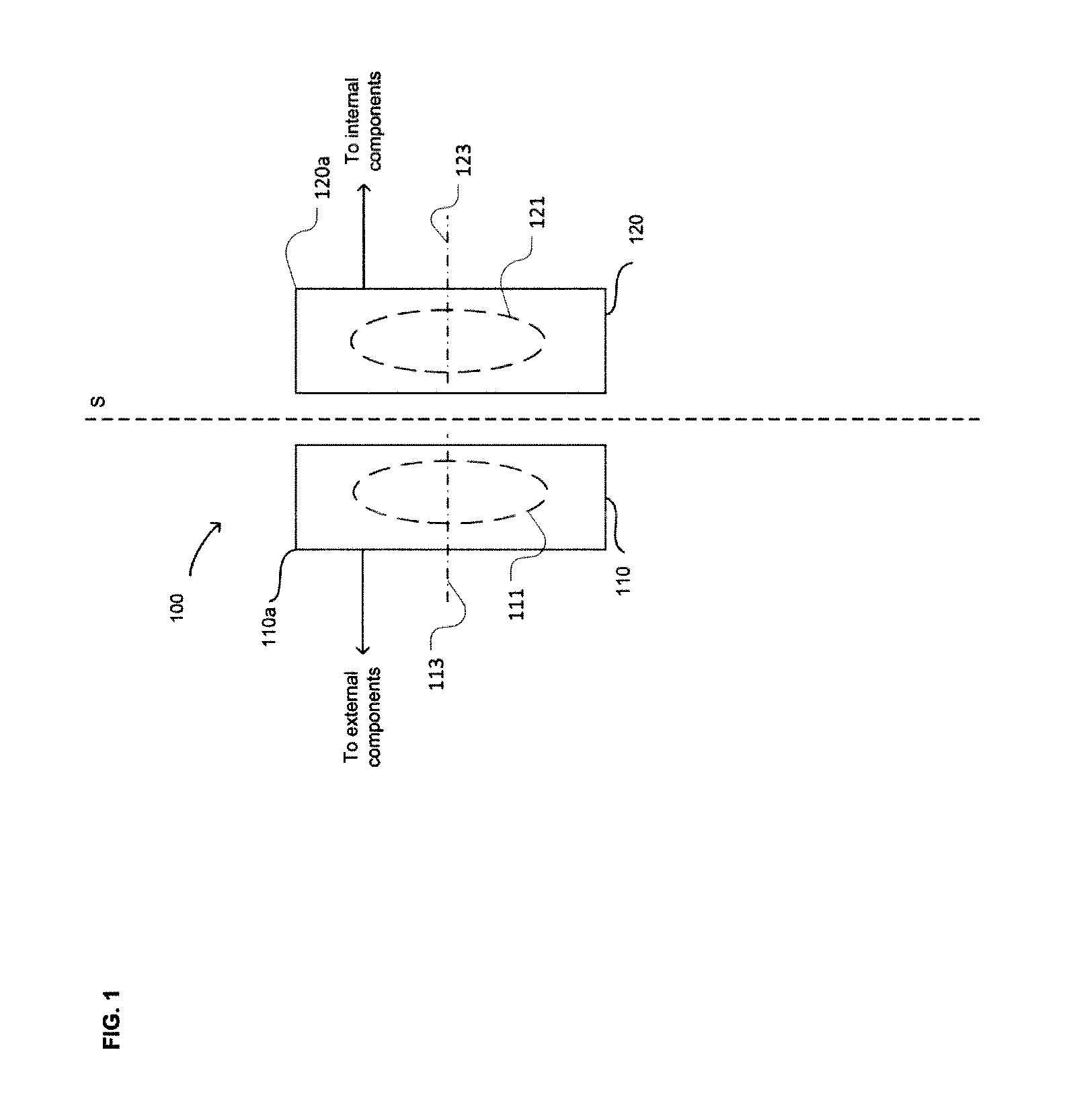
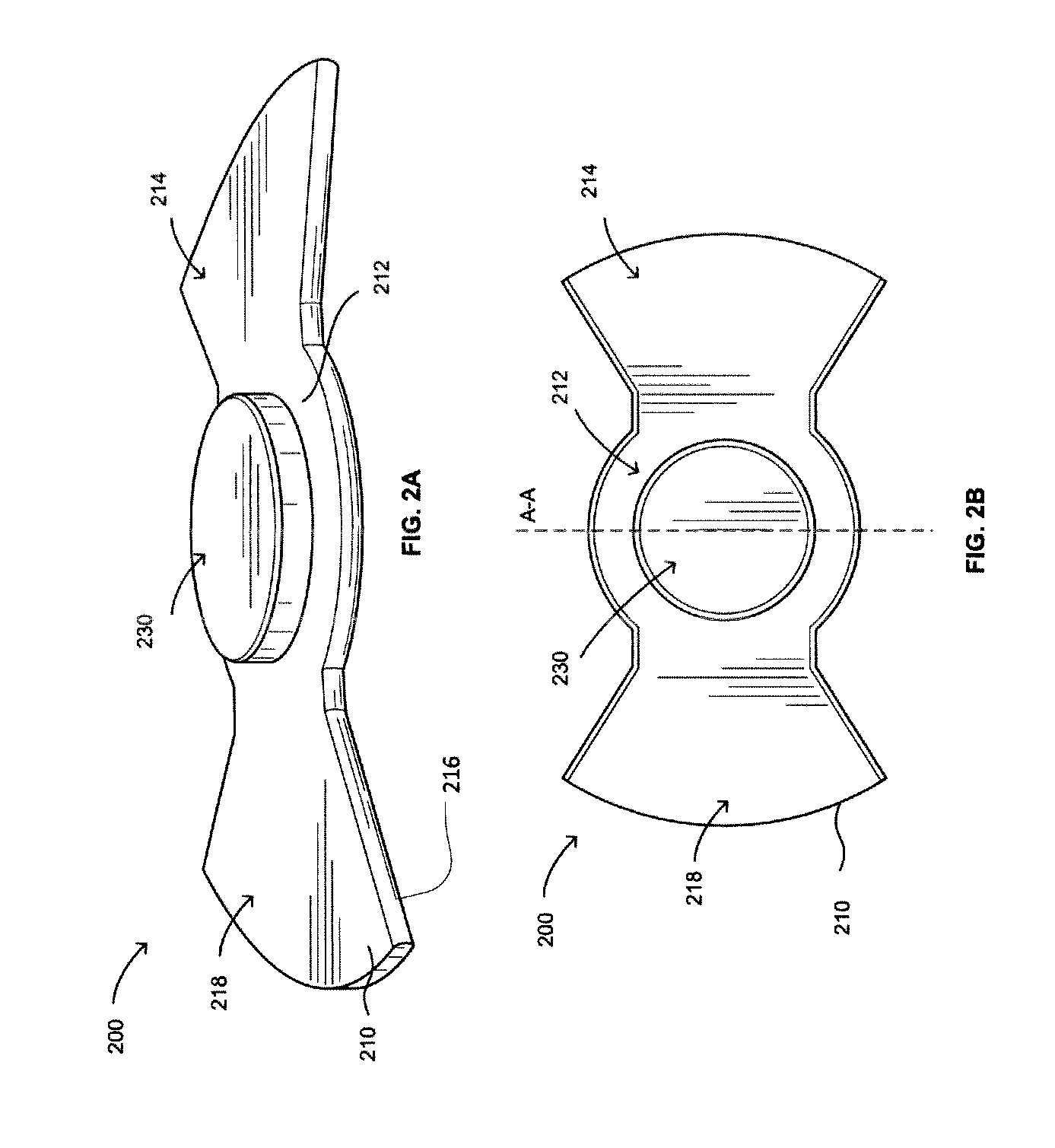
[0016]A typical TET system 100 (FIG. 1) may include an external coil 110 and an internal coil 120. The external coil 110 may be positioned outside the skin S of a body, such as a mammalian body or the body of a human patient, and the internal coil 120 may be implanted within the body. The external coil 110 includes a housing 110a which housing a coiled conductor schematically shown at 111, whereas the internal coil 120 includes a housing 120a holding a coiled conductor 121 to allow for energy to be transferred from the external coil 110 to the internal coil 120. Conductor 111 extends around an external coil axis 113, whereas internal coil extends around an internal coil axis 123. Each of the coiled conductors may be generally in the form of a loop, spiral or spiral extending generally in a plane perpendicular to the coil axis, or in the form of a helix extending generally along a cylinder coaxial with the coil axis, or in another form, depending on the number of revolutions of the c...


PUM


Abstract

An alignment device for an external coil in a transcutaneous energy transfer (TET) system. The device may be adhered to the skin or clothing of a patient and may ensure alignment between an external coil and an internal coil to provide optimal energy transfer in a TET system.

Description

CROSS-REFERENCE TO RELATED APPLICATIONS[0001]The present application claims the benefit of the filing date of U.S. Provisional Patent Application No. 61 / 658,178, filed Jun. 11, 2012, the disclosure of which is hereby incorporated herein by reference.BACKGROUND OF THE INVENTION[0002]The present invention relates to an alignment device for an external coil in a transcutaneous energy transfer (TET) system.[0003]Certain medical devices implanted within the body must be supplied with electrical power. For example, ventricular assist devices used to supplement the pumping action of the heart must be supplied with power, typically a few watts to tens of watts. This power can be supplied through a wire penetrating the skin. However, such a wire poses a risk of infection, particularly when left in place for months or years. Measures to alleviate this risk add to the burden placed upon the patient and caregivers. TET systems transmit power into the body without the use of wires penetrating th...

Claims


Application Information

Patent Timeline
IPC IPC(8): A61M1/12
CPCA61M1/127A61M60/178A61M60/216A61M60/875A61N1/378A61M60/148
Inventor CAMERON, ALLANPAGE, CHRISTOPHER
Owner HEARTWARE INC
Learn More