
Control system and pairing method for a control system

a control system and control system technology, applied in the direction of digital transmission, data switching by path configuration, electrical apparatus, etc., can solve the problems of prior art control system installation, difficult for many users, and difficult to install such a system, and achieve the effect of convenient installation, configuration and updating

Inactive Publication Date: 2013-12-12
ZEROGROUP HLDG
View PDF6 Cites 1 Cited by
  • Summary
  • Abstract
  • Description
  • Claims
  • Application Information

AI Technical Summary

Benefits of technology

The invention relates to a control system and a pairing method that are easy to install, configure, and update. The control system can be connected through a wired network, such as RS485, which prevents interference between nearby control systems. The server can manage the configuration and function of the control system, and users can access the server to configure new nodes or hubs. The invention provides automatic pairing and configuration of nodes and hubs without the need for manual activation or changes. The technical effects include improved efficiency, ease of installation, and remote management of the control system.

Problems solved by technology

However, the more complicated the system is, the more difficult and costly it generally is to install such a system, and make upgrades and changes in the system.
There are certain disadvantages related to the prior art control systems.
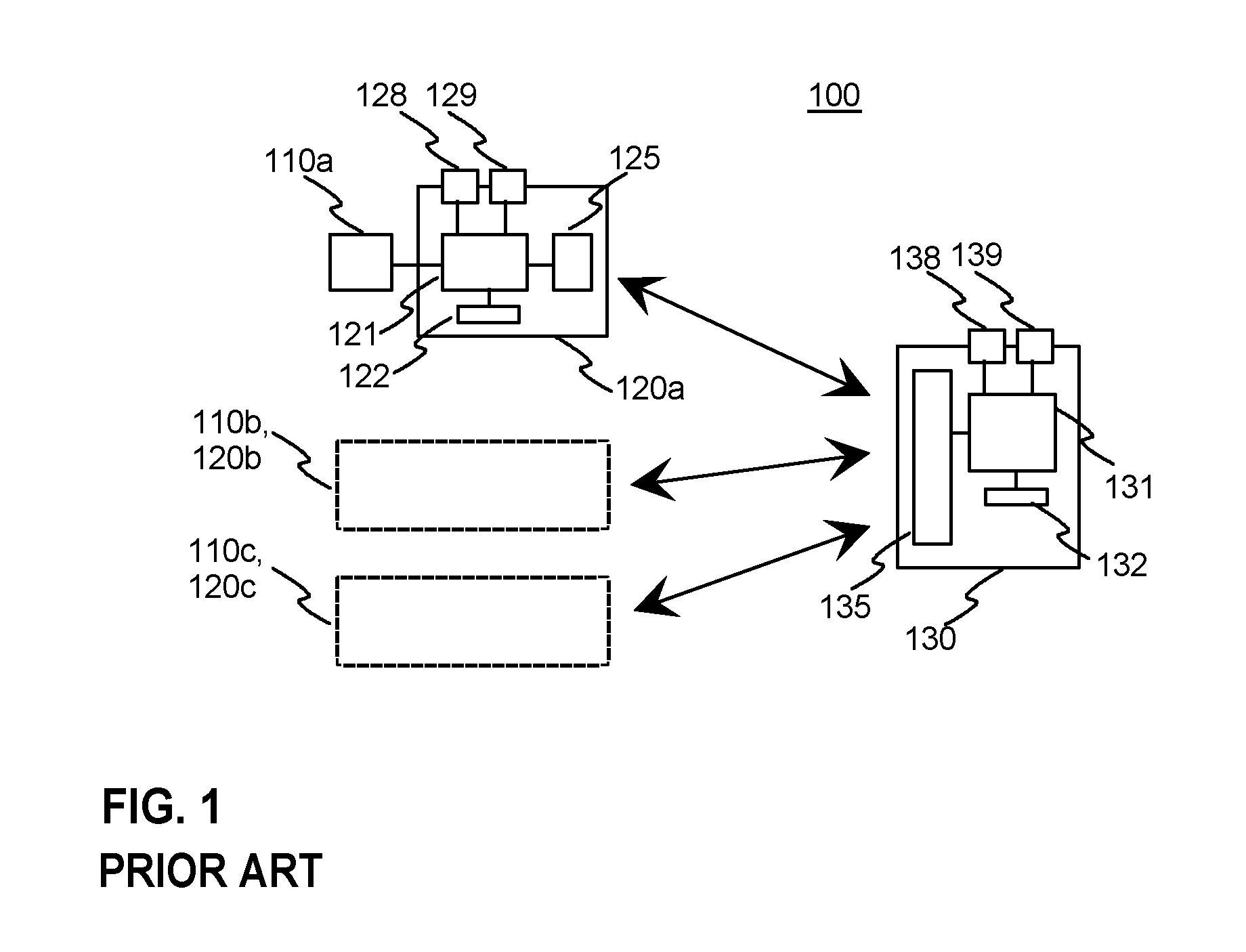
Firstly, in a prior art system manual activation of the pairing process is required, which may be difficult for many users.
After this, all nodes need to be paired to related control device, and this tends to take much time.
And as a further problem, sometimes the pairing process may fail.

Method used


Image

  • Control system and pairing method for a control system
  • Control system and pairing method for a control system
  • Control system and pairing method for a control system

Examples


Embodiment Construction

[0035]FIG. 1 was described in the prior art description above. Next the invention is presented by first describing an exemplary control system according to the invention, and then an exemplary pairing method for a control system is described.

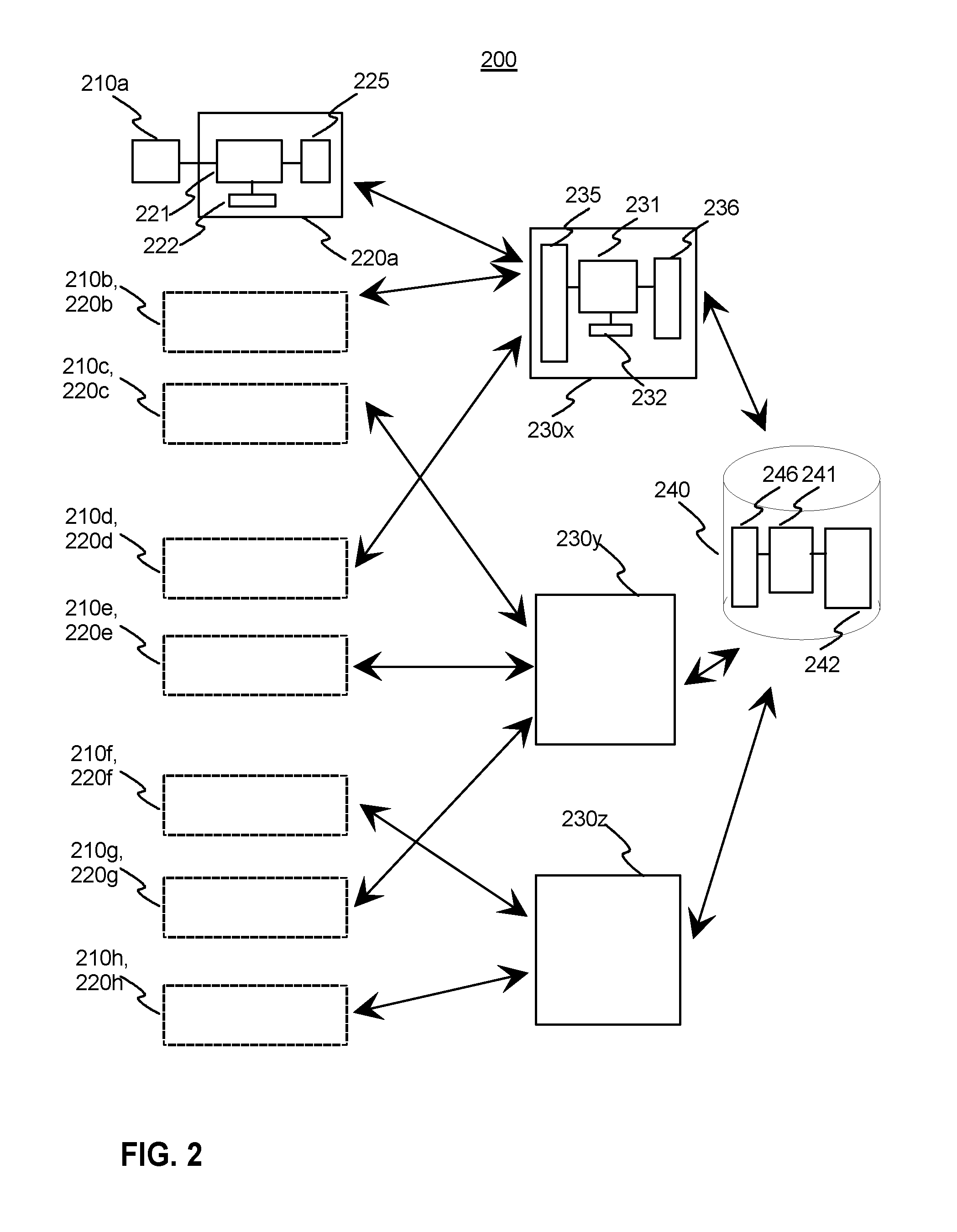
[0036]FIG. 2 illustrates a block diagram of an exemplary control system according to the invention. The control system 200 has three hubs 230x, 230y and 230z. These hubs may be installed in different floors of a building, for example. The hubs have a processor 231 with a memory 232. The hubs are in communication with nodes 220a-220h through a wireless or wired network. The hubs have a transceiver 235 for the communication in the network. The hubs may also communicate with each other via the network. For example, in case of a fire within the control area of a first hub, this information can be transferred to other hubs of the building for the purpose of providing alarm.

[0037]The nodes have a transceiver 225 for communication with the hubs. It is ...


PUM


Abstract

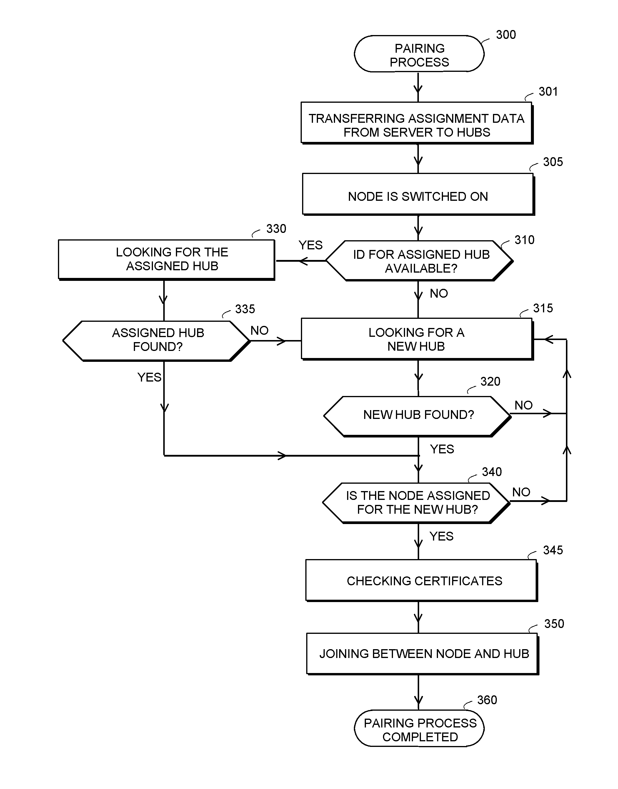
The present invention relates to a control system (200) and a pairing method for installation, configuration and update of a control system. In the inventive solution the control system comprises nodes (220q-220h) with control elements (210a-210h), one or several hubs (230x-230y), and a server (240). Identification data of assigned nodes (220a, 220b, 220d) is transferred from the server (240) to a hub (230x). The hub provides a pairing process with nodes that have any of the IDs stored as assigned nodes. This way an automatic pairing process is achieved, which does not require manual activation procedures of a user.

Description

TECHNICAL FIELD OF THE INVENTION[0001]The present invention relates to a control system and a pairing method for installation, configuration and update of a control system. The invention is applicable to e.g. control systems for controlling environmental conditions of different entities, such as apartments and offices. The environmental conditions may relate to temperature, humidity, CO2 level, electricity, access, water supply, and lighting, for example. The invention is also applicable for controlling other electrical equipment such as domestic appliances and multimedia equipment.BACKGROUND OF THE INVENTION[0002]In order to save energy and to improve living environment in buildings, there are control systems for adjusting heating, air conditioning, and lighting, for example. Simple systems may include a heater, a sensor, and an adjustment panel for adjusting the desired temperature. More facilitated systems may include several sensors, actuators and control panels. There are also ...

Claims


Application Information

Patent Timeline
Patent Type & Authority Applications(United States)
IPC IPC(8): H04L12/28
CPCH04L12/2803H04L67/025H04L67/12H04L61/5038H04L61/59H04L12/28H04L61/00H04L65/40
Inventor VIMBERG, PRIIT
Owner ZEROGROUP HLDG
Learn More