
Virtualization and dynamic resource allocation aware storage level reordering

a virtual and dynamic resource technology, applied in computing, memory adressing/allocation/relocation, instruments, etc., can solve the problems of high resource and link usage, energy overhead, and hammer the effectiveness of joint operations, so as to reduce the performance overhead of vm reprovisioning or repositioning actions, the effect of reducing recovery operations

Active Publication Date: 2013-12-05
IBM CORP
View PDF0 Cites 6 Cited by
  • Summary
  • Abstract
  • Description
  • Claims
  • Application Information

AI Technical Summary

Benefits of technology

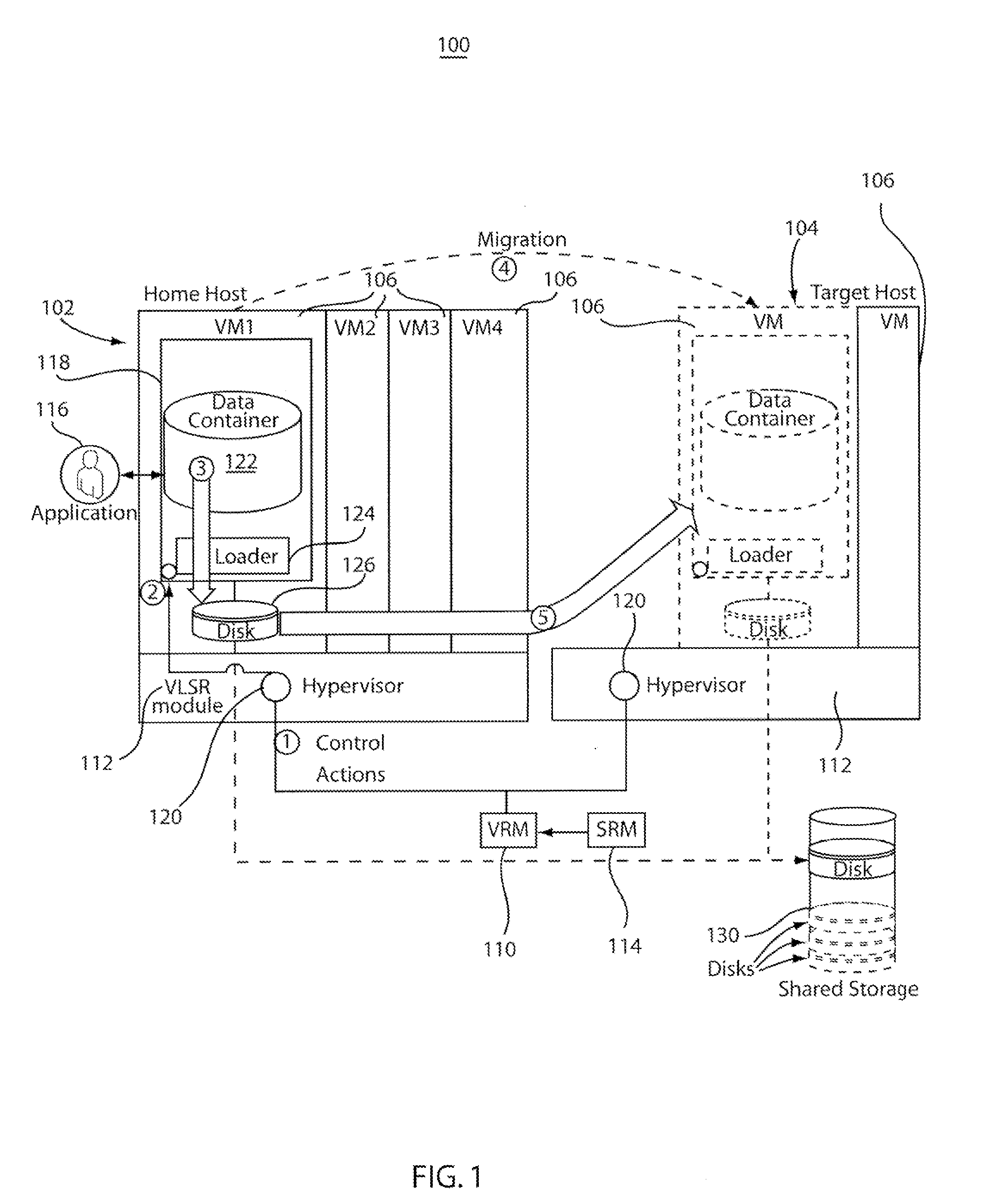
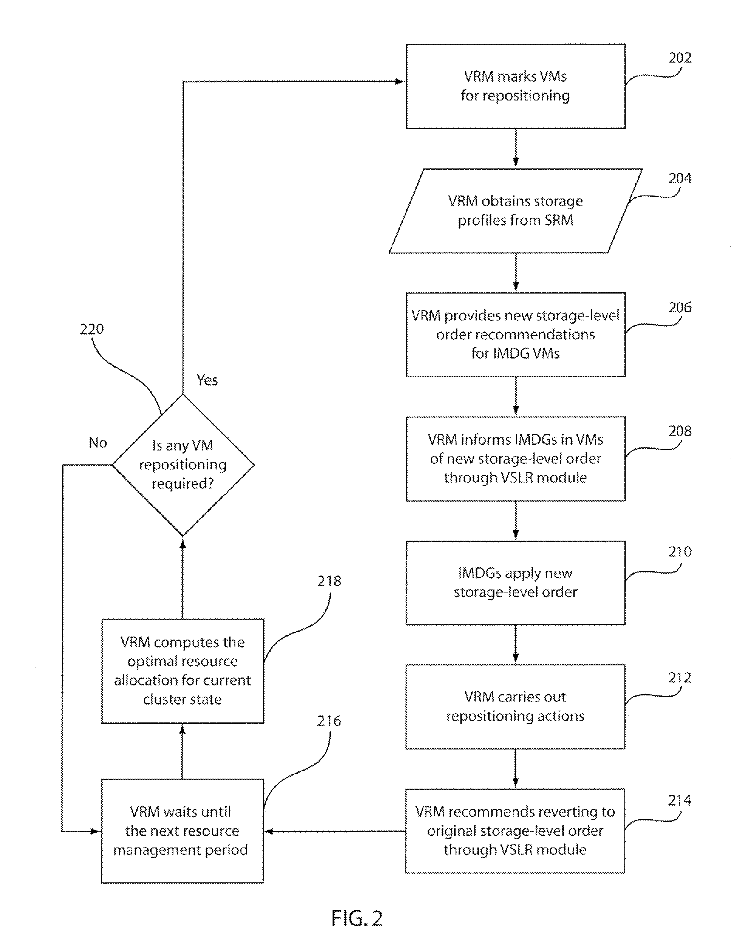
[0013]A system for dynamically reordering storage levels for applications in virtualized systems includes a virtual machine to be reprovisioned or repositioned, stored in a memory storage device. A virtualized resource manager (VRM) is configured to recommend a new storage level order in a memory media hierarchy for the VM that reduces a VM live state during reprovisioning or migration, accounts for storage levels based upon profiling information, and reduces recovery operations after dynamic resource allocation actions. A virtualization- and dynamic-resource-allocation-aware storage level reordering (VSLR) module is configured to propagate and apply the new storage level order recommendation to appropriate memory intensive VMs such that reordering mitigates the performance overhead of VM reprovisioning or repositioning actions.

Problems solved by technology

While both of these trends have proven to be effective exclusively in their domains and continue to gain increasing momentum, they exhibit a striking conflict in their characteristics that can hamper their effectiveness under joint operation in a cloud environment.
This has at least two detrimental effects: (1) higher performance overhead perceived by the applications using IMDG nodes as the response times increase under dynamic allocation conditions; and (2) energy overheads due to extensive copying and recopying of live state, as well as higher resource and link usage.
Quite significant degradations can also be observed in the application performance, such as service times, depending on the application characteristics and the level of overcommitment on the host.

Method used


Image

  • Virtualization and dynamic resource allocation aware storage level reordering
  • Virtualization and dynamic resource allocation aware storage level reordering
  • Virtualization and dynamic resource allocation aware storage level reordering

Examples


Embodiment Construction

[0019]The present principles provide a system having multi-level data storage including a low latency / high bandwidth storage medium, e.g., RAM, and a higher latency / lower bandwidth storage medium, e.g., disk, which operate in a hierarchical fashion. In the context of, e.g., in-memory data grid (IMDG) appliances, a storage level with best latency / size ratio is considered primary and hence has the highest priority in the hierarchy. For example, IMDG technologies, such as ObjectGrid™, operate primarily on RAM and rely on disk storage to respond to overflow conditions.

[0020]A virtualization- and dynamic-resource-allocation-aware storage level reordering (VSLR) module permits applications such as IMDGs to work in conjunction with a system virtual resource manager (VRM) to mitigate overhead resulting from virtual machine (VM) migration by effectively reducing live state data of a hosting VM to be migrated. Reducing the active state of these applications can lead to several orders of reduc...


PUM


Abstract

A system and method for reordering storage levels in a virtualized environment includes identifying a virtual machine (VM) to be transitioned and determining a new storage level order for the VM. The new storage level order reduces a VM live state during a transition, and accounts for hierarchical shared storage memory and criteria imposed by an application to reduce recovery operations after dynamic resource allocation actions. The new storage level order recommendation is propagated to VMs. The new storage level order applied in the VMs. A different storage-level order is recommended after the transition.

Description

CROSS-REFERENCE TO RELATED APPLICATIONS[0001]This application is a Continuation application of allowed co-pending U.S. patent application Ser. No. 12 / 777,394 filed on May 11, 2010, incorporated herein by reference in its entirety.BACKGROUND[0002]1. Technical Field[0003]The present invention relates to efficient interoperation of computing technologies, and more particularly to systems and methods for storage level reordering for virtual and dynamic resource allocation for memory-intensive applications.[0004]2. Description of the Related Art[0005]Emerging Internet-scale service applications operate on large amounts of data that are maintained in memory to achieve high throughput and offer low response time guarantees to users. Key catalyzers to this trend have been the significant decrease of memory cost, increase of memory capacity in machines and development and adoption of in-memory distributed storage technologies such as memcached, XAP and ObjectGrid™. As a result, In-Memory Dat...

Claims


Application Information

Patent Timeline
Patent Type & Authority Applications(United States)
IPC IPC(8): G06F9/455
CPCG06F9/45533G06F9/5077G06F9/45558G06F12/08G06F2009/45583G06F2212/657
Inventor CASTILLO, CLARISISCI, CANTURK
Owner IBM CORP
Learn More