Methods and apparatus for computer-aided radiological detection and imaging

a computer-aided radiological and imaging technology, applied in the field of image detection, can solve the problems of life-threatening, difficult, time-consuming, etc., and achieve the effect of improving patient safety, increasing radiologist productivity and confiden

Active Publication Date: 2013-12-05
RGT UNIV OF CALIFORNIA
View PDF8 Cites 8 Cited by
  • Summary
  • Abstract
  • Description
  • Claims
  • Application Information

AI Technical Summary

Benefits of technology

[0019]The CAD system and methods of the present invention were tested to show feasibility of automatic detection of both ET tube ...

Problems solved by technology

Chest radiographs are used to confirm placement of life support tubes in patients, and incorrect placement of these tube can cause severe complications and can even be fatal.
Accordingly, detecting tube placement is critical for patients in ICU's as incorrect tube placements can cause serious complications and can even be life threatening.
Assessing tube placement on chest radio...

Method used


Image

  • Methods and apparatus for computer-aided radiological detection and imaging
  • Methods and apparatus for computer-aided radiological detection and imaging
  • Methods and apparatus for computer-aided radiological detection and imaging

Examples


embodiment 1

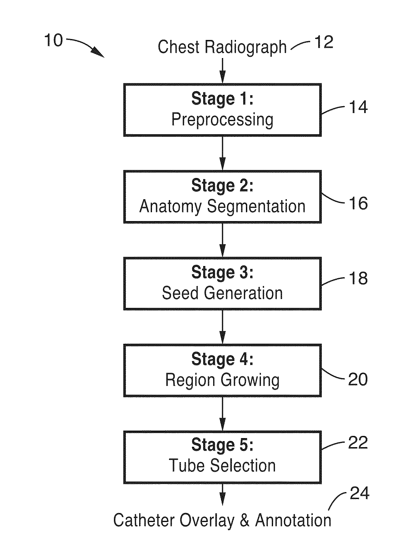
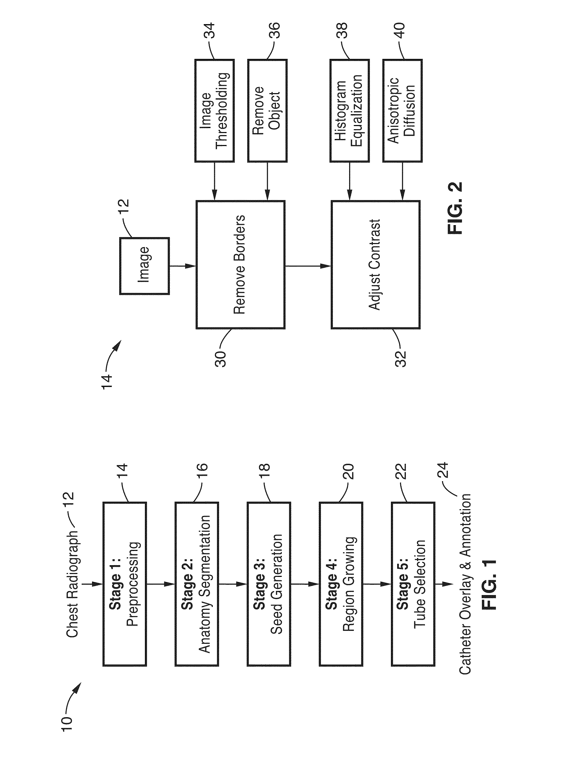
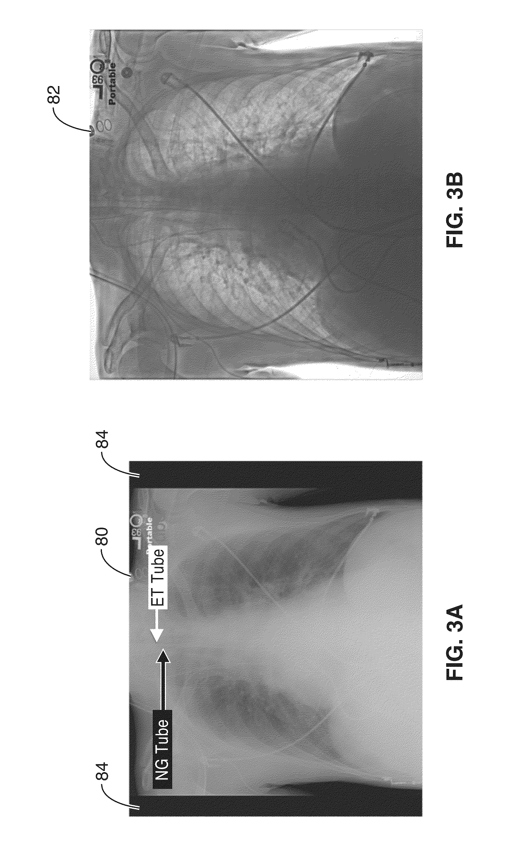
[0090]2. The method of embodiment 1, wherein image comprises a radiograph.

[0091]3. The method of embodiment 1: wherein the one or more IMD comprises a catheter; and wherein generating one or more seed points comprises: detecting a pair of parallel lines; calculating a midpoint between the pair of parallel lines; and assigning a location of one of said one or more seed points at said midpoint.

embodiment 3

[0092]4. The method of embodiment 3, wherein projecting one or more grown seed points comprises: matching one or more templates of the catheter with the one or more seed points; and growing the path of the one or more seed points as a function of a profile of the catheter.

embodiment 4

[0093]5. The method of embodiment 4, wherein the template comprises orientation, translation and tube profiles as parameters used in growing the path of the one or more seed points.


PUM


Abstract

A computer aided detection (CAD) method and system is configured to input chest radiographs and generate overlay layer for labeling and tracing tubes detected within the image. The input image is first preprocessed and then segmented according to anatomy. Seeds are generated from the segmented image and then used to grow the region. Tubes are selected from the grown region and data is overlayed on the image based on the grown seed path.

Description

CROSS-REFERENCE TO RELATED APPLICATIONS[0001]This application is a 35 U.S.C. §111(a) continuation of PCT international application number PCT / US2012 / 023741 filed on Feb. 3, 2012, incorporated herein by reference in its entirety, which is a nonprovisional of U.S. provisional patent application Ser. No. 61 / 439,596 filed on Feb. 4, 2011, incorporated herein by reference in its entirety. Priority is claimed to each of the foregoing applications.[0002]The above-referenced PCT international application was published as PCT International Publication No. WO 2012 / 106580 on Aug. 9, 2012 and republished on Oct. 4, 2012, and is incorporated herein by reference in its entirety.STATEMENT REGARDING FEDERALLY SPONSORED RESEARCH OR DEVELOPMENT[0003]Not ApplicableINCORPORATION-BY-REFERENCE OF MATERIAL SUBMITTED ON A COMPACT DISCNOTICE OF MATERIAL SUBJECT TO COPYRIGHT PROTECTION[0004]A portion of the material in this patent document is subject to copyright protection under the copyright laws of the Un...

Claims


Application Information

Patent Timeline
IPC IPC(8): G06T7/00
CPCA61B6/463A61B6/5217A61B8/463A61B8/5223G06T7/0083G06T2207/10072G06T7/0012G06T2207/10132G06T2207/20136G06T2207/20156G06T2207/30021G06T2207/30172G06T2207/10116G06T7/12G06T7/181
Inventor ENZMANN, DIETER R.BROWN, MATTHEW S.GOLDIN, JONATHANRAMAKRISHNA, BHARATH
Owner RGT UNIV OF CALIFORNIA
Why Eureka
Try Eureka