
Integration of MRI into Radiation Therapy Treatment

a radiation therapy and radiation therapy technology, applied in the field of ternal beam radiotherapy, can solve the problems of significant impact on the quality of life of patients, increased the possibility of secondary rt-induced cancer, and damage to the collateral tissue, and achieve the effect of high registration accuracy and convenient registration

Active Publication Date: 2013-11-28
DEERFIELD IMAGING INC
View PDF5 Cites 18 Cited by
  • Summary
  • Abstract
  • Description
  • Claims
  • Application Information

AI Technical Summary

Benefits of technology

The patent describes a way to prevent RF signals from interfering with magnetic resonance imaging (MRI) during radiation therapy procedures. This is achieved through the use of a movable RF-shielded door that can be opened and closed to allow for easy access to the treatment apparatus without shutting down its critical electronic components. The use of a movable magnet also enables the separation of the treatment apparatus from the magnet during MRI imaging, without the need for complex hybrid systems. The technical effects of this patent are improved image quality and more efficient and accurate radiation therapy procedures.

Problems solved by technology

Although MRI provides good location of the tumour for treatment planning purposes, these treatment planning images are normally collected several days prior to treatment, and, as such, may not be completely representative of tumour location on the day of treatment.
However, this increased treatment margin also produces collateral tissue damage that may have a significant impact of the quality of life of the patient and increase the possibility of secondary RT-induced cancer.
However, this design is complex, expensive and may involve serious compromises on the functional performance of both the MRI and linear accelerator.
As such, the position of the tumour in the treatment imaging plans may not be representative of the actual lesion position on each day of treatment.
Although simplistic, this is a manual, time-consuming, and error-prone technique.
This alternative method is based solely on patient anatomy and involves registering two image datasets with considerably different image contrasts, and is prone to registration errors.
In U.S. Pat. No. 5,778,047 (Mansfield) issued Jul. 7, 1998 Varian discloses patient couch-top in entitled Radiotherapy Couch Top; however, materials in the design include carbon fiber, and therefore not MR compatible.

Method used


Image

  • Integration of MRI into Radiation Therapy Treatment
  • Integration of MRI into Radiation Therapy Treatment
  • Integration of MRI into Radiation Therapy Treatment

Examples


Embodiment Construction

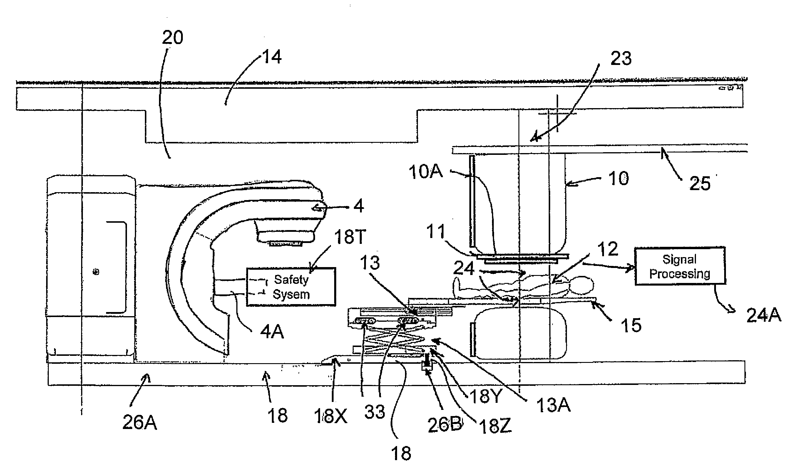
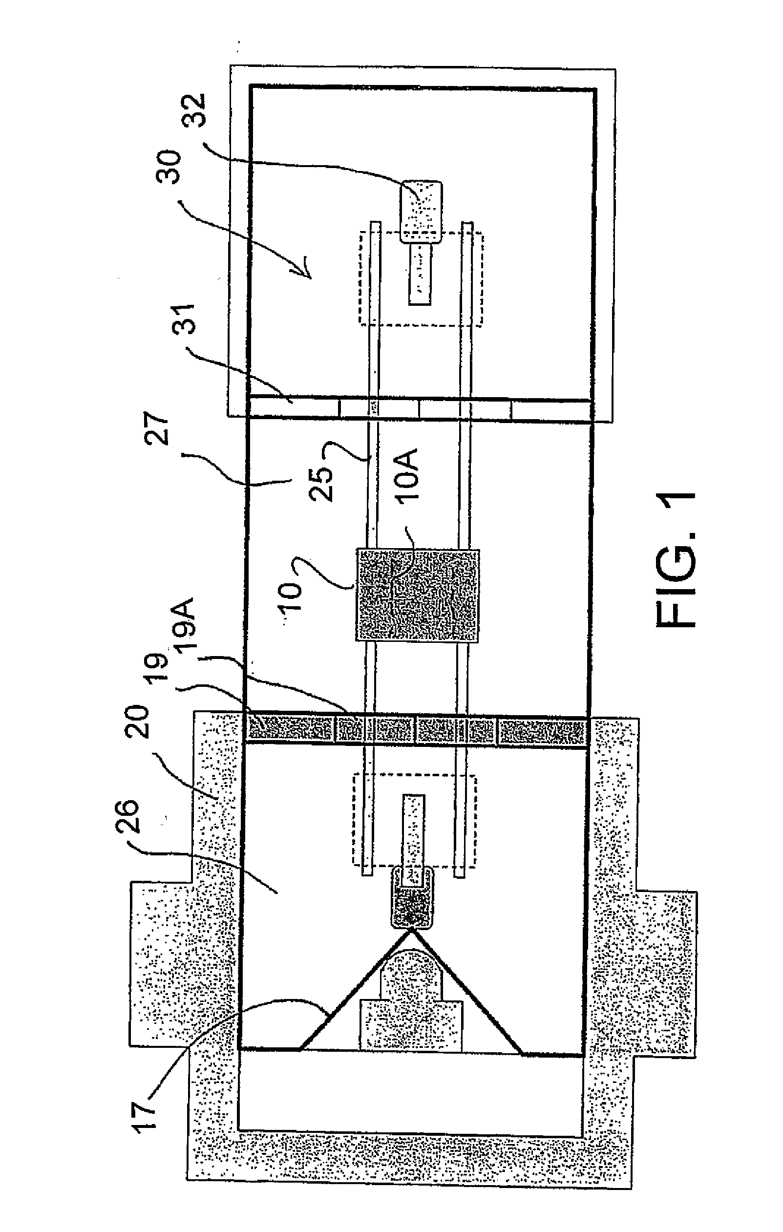
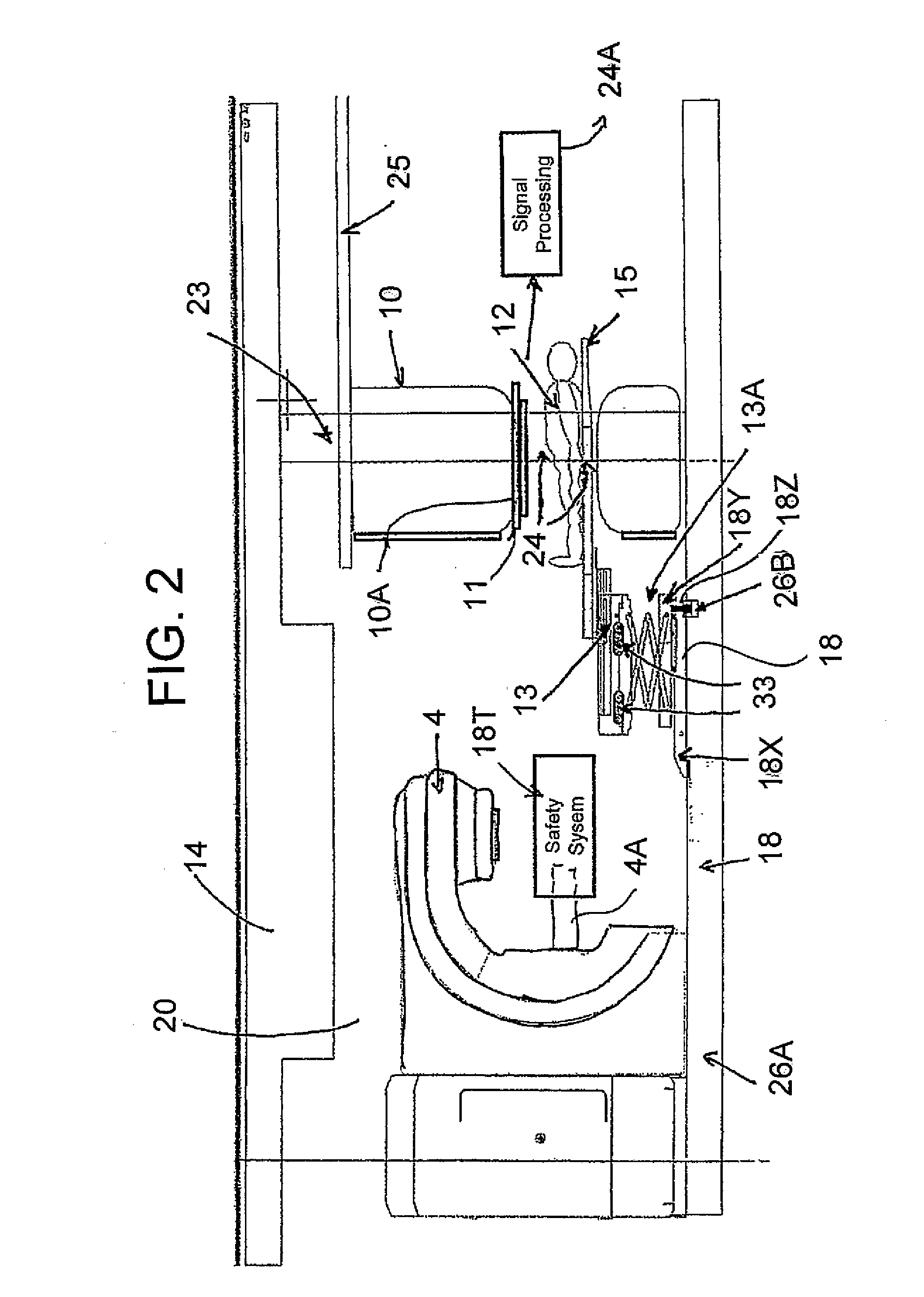
[0136]In FIGS. 1 to 5 is shown a schematic diagram of the MRI and external beam RT therapy system within the external beam bunker room configuration. This diagram includes a magnet 10, having a bore 10A into which a patient 12 can be received on a patient couch top 15, which is attached to a patient couch 13.

[0137]The movable magnet is carried on a rail system 25 with a support 23 suspended on the rail system. Further details of this construction are available from published US application 2008 / 0038712 published Feb. 14, 2008 assigned to the present assignees, the disclosure of which is incorporated herein by reference.

[0138]A suitable radiation therapy system 4 is available from Varian. This can use different radiation including proton beams, brachytherapy or X-ray. The Varian radiation therapy system is capable of delivering therapeutic radiation to the patient using an x-ray beam formed through a multi-leaf collimator to modulate the intensity of the radiation delivered.

[0139]The...


PUM


Abstract

Apparatus for radiation therapy combines a patient table, an MRI and a radiation treatment apparatus mounted in a common treatment room with the MR magnet movable from a position outside a radiation shielded door to an imaging position. An RF-shielded door is movable between a position, separating part of the treatment apparatus from the magnet and an open position allowing access of the patient to the treatment apparatus. In one configuration there is a row of treatment rooms and the magnet is mounted to move along a passageway outside the row of radiation shielded doors of the rooms.

Description

[0001]This application claims the benefit under 35 USC 119(e) from Provisional Application 61 / 497,236 filed Jun. 15, 2011.[0002]This invention relates to a system to integrate of MRI into radiation therapy treatment. The treatment using radiation can be conventional targeted beam therapy or brachytherapy where radiating material is introduced into the body of the patient.BACKGROUND OF THE INVENTION[0003]External beam radiotherapy (RT) devices generally include a linear electron beam accelerator which is mounted on a gantry, which can rotate about an axis approximately parallel to the patient lying on the patient couch. The patient is treated using either an electron beam or an X-Ray beam produced from the original electron beam. The electron or X-Ray beam is focused at a target by the combination of the use of a collimator and the rotation of the beam. The patient is placed on a couch that can be positioned such that the target lesion can be located in the plane of the radiation bea...

Claims


Application Information

Patent Timeline
Patent Type & Authority Applications(United States)
IPC IPC(8): A61B5/00A61N5/10A61B5/055
CPCA61B5/0046A61B5/0555A61B5/4836A61N5/1077A61N5/1001A61N5/1039A61B5/055A61N2005/1055A61N2005/1063A61N2005/1094A61B5/0036G01R33/4808
Inventor KLIMENKO, GORDONDAHAN, MEIRGUYOT, BRENDANHORNBLOWER, VICTORIAPETROPOULOS, LABROSSAUNDERS, JOHNVAN HETEREN, JOHNWINTER, JEFFYI, HONGXIANG
Owner DEERFIELD IMAGING INC
Learn More