
Cartridge filter combining a depth filter and a sub-micron filter, and ro pre-treatment method

a filter and depth technology, applied in the field of filtration, can solve the problems of discarded filters at the end of their useful life and limited maximum pressure drop,

Inactive Publication Date: 2013-11-21
GENERAL ELECTRIC CO
View PDF4 Cites 24 Cited by
  • Summary
  • Abstract
  • Description
  • Claims
  • Application Information

AI Technical Summary

Benefits of technology

The present invention provides a cartridge filter assembly comprising an inner screen or surface filter and a depth filter element. The depth filter element is made of a mass of melt-blown polymer filaments that have different characteristics in the depth dimension. The mass has a longitudinal dimension and a latitudinal dimension, and a traversing melt-blown polymer filament that extends in the depth dimension through two or more zones. The technical effect of this invention is that it provides a more efficient and effective filtering system for removing impurities from a liquid or gas stream.

Problems solved by technology

Some cartridge filters may be cleaned, but they are often discarded at the end of their useful life.
The maximum pressure drop may be limited by the mechanical ability of a filter element to withstand a differential applied across it.

Method used


Image

  • Cartridge filter combining a depth filter and a sub-micron filter, and ro pre-treatment method
  • Cartridge filter combining a depth filter and a sub-micron filter, and ro pre-treatment method
  • Cartridge filter combining a depth filter and a sub-micron filter, and ro pre-treatment method

Examples


Embodiment Construction

[0022]The following descriptions of the embodiments refer to the accompanying drawings. Embodiments are described in detail to enable practice of the invention. Although the invention is described with reference to specific embodiments, it will be understood that the invention is not limited to these examples and includes numerous alternatives, modifications and equivalents.

[0023]Approximating language, as used herein throughout the specification and claims, may be applied to modify any quantitative representation that could permissibly vary without resulting in a change in the basic function to which it is related. Accordingly, a value modified by a term or terms, such as “about”, is not limited to the precise value specified. In at least some instances, the approximating language may correspond to the precision of an instrument for measuring the value. Range limitations may be combined and / or interchanged, and such ranges, and all sub-ranges, are included herein unless context or ...


PUM

PropertyMeasurementUnit
sizeaaaaaaaaaa
sizeaaaaaaaaaa
diameteraaaaaaaaaa

Abstract

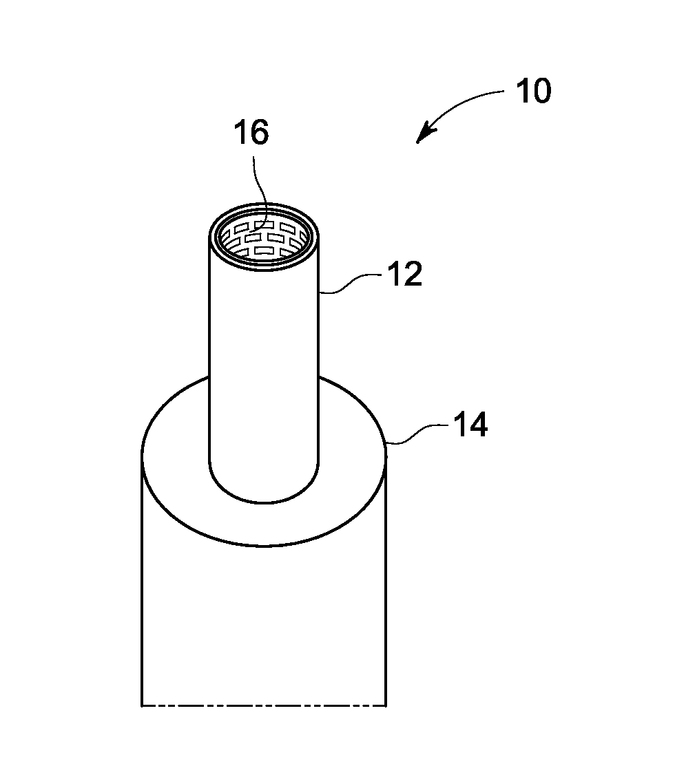
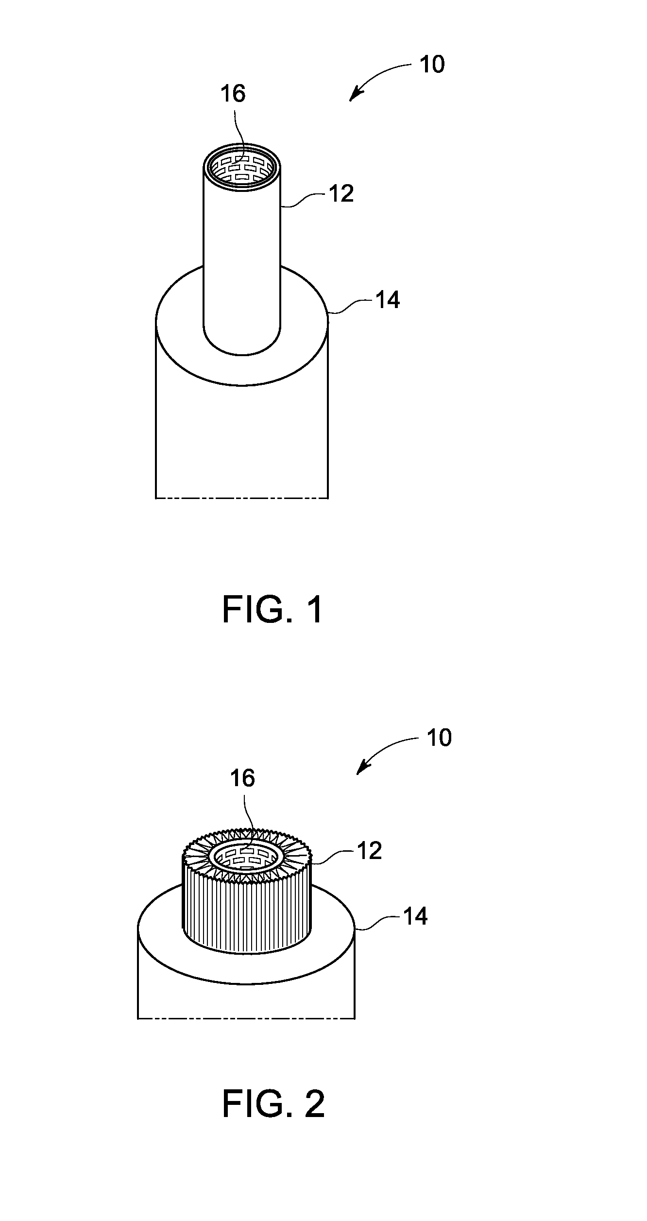
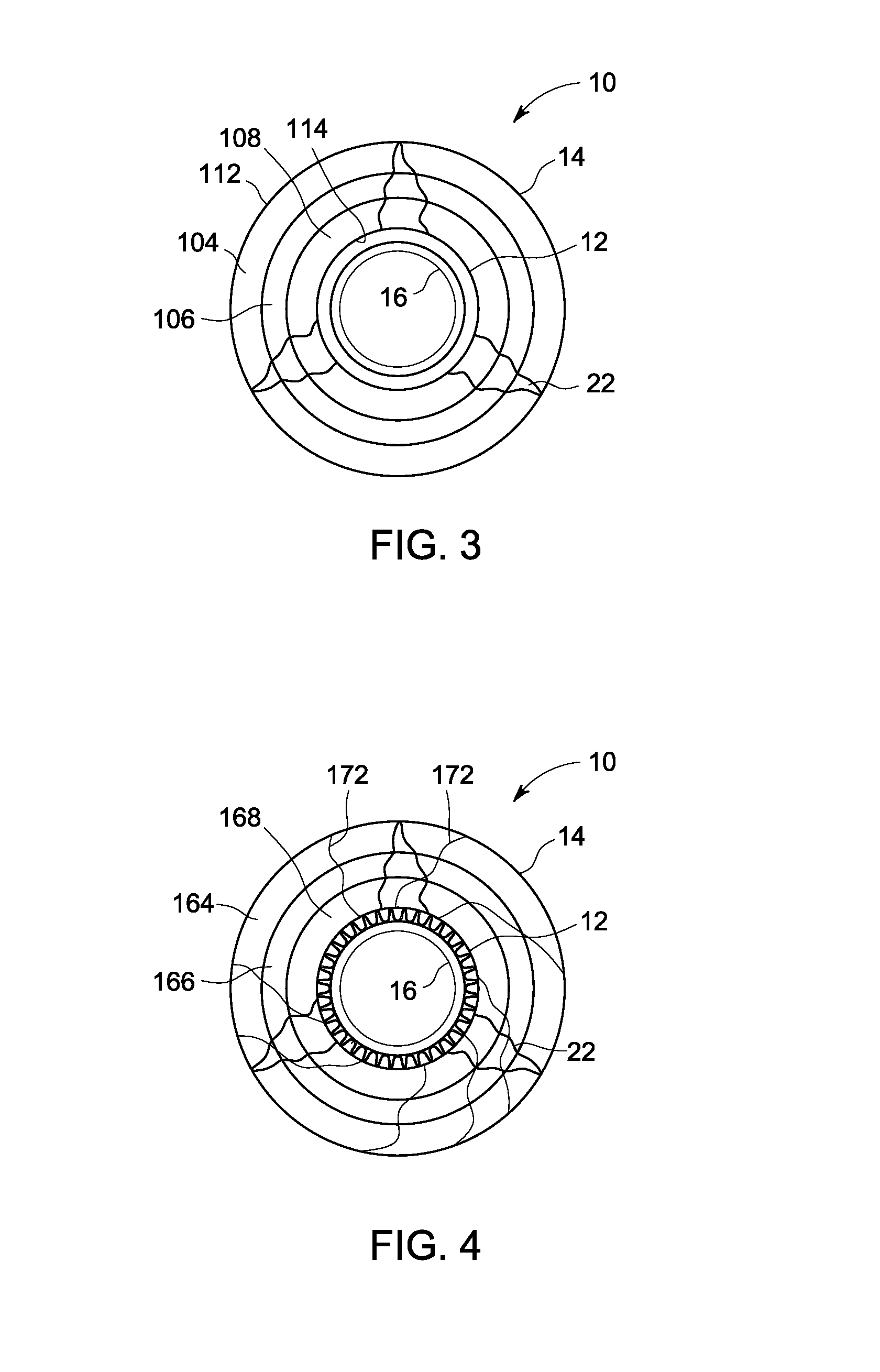
A cartridge filter assembly includes a depth filter element and a downstream second filter element. The depth filter element has a mass of melt-blown polymer filaments. The depth filter removes 0.5 to 10 micron sized contaminants at an efficiency of 90% or more. The depth filter preferably comprises multiple zones occupying different depths, with one or more melt-blown polymer filaments traversing two or more of the zones. The second filter element comprises nano-fibers having a diameter of 1 micron or less, and removes a material percentage of contaminants that are less than 1 micron in size, preferably less than 0.5 microns in size. The depth filter element may be in the form of a tube and the second filter element may be in the form of a pleated sheet located inside of the depth filter. The cartridge filter assembly may be used to pre-treat a feed water upstream of an RO membrane. The SDI of the feed water may be reduced to 3 or less or 2 or less.

Description

CROSS REFERENCE TO RELATED APPLICATIONS[0001]This is a national stage application under 35 U.S.C. §371(c) prior-filed, co-pending PCT patent application serial number PCT / US11 / 51012, filed on Sep. 9, 2011, which claims priority to U.S. Provisional Application No. 61 / 381,708, filed on Sep. 10, 2010, the entire contents of which are incorporated herein by reference.BACKGROUND OF THE INVENTION[0002]Embodiments of the subject matter disclosed herein relate generally to filtration, and in particular to a cartridge filter combining a depth filter with a second filter comprising fibers with a diameter of less than 1 micron, and to a method of pre-treating feed water before reverse osmosis (RO).[0003]The following discussion is not an admission that anything described below is common general knowledge or citable as prior art.[0004]Filters may be designed to remove solids including colloidal particles and microorganisms. Two common types of filters used in filtering liquids are depth filters...

Claims


Application Information

Patent Timeline
Patent Type & Authority Applications(United States)
IPC IPC(8): B01D27/02
CPCB01D27/02B01D29/21B01D29/58B01D2311/04B01D2311/2649B01D39/163B01D39/202B01D39/2086B01D2239/025B01D2239/0622B01D2239/0627B01D2239/1216B01D2239/1233B01D61/025B01D27/04B01D35/00B01D29/50B01D61/04
Inventor STIFTER, TRAVIS GERALDAUNE, THOMAS MARTINSZCZEPANSKI, JOSEPH T.LAIDLAW, WILLIAM B.BHARWADA, UPEN JAYANT
Owner GENERAL ELECTRIC CO
Learn More