
Turboprop-powered aircraft

a turboprop aircraft and thermal management technology, applied in the direction of machines/engines, energy-saving board measures, lighting and heating apparatus, etc., can solve the problems of correspondingly complex and expensive (in terms of money or power consumption) thermal management arrangements practicable, and achieve simple system solutions, optimise/maximimise fuel economy and hence the duration of each mission. , the effect of improving the efficiency of surveillance functions

Inactive Publication Date: 2013-10-31
BAE SYSTEMS PLC
View PDF8 Cites 31 Cited by
  • Summary
  • Abstract
  • Description
  • Claims
  • Application Information

AI Technical Summary

Benefits of technology

The present invention provides a way to use turboprop-powered MALE aircraft with long endurance and reduced need for fuel extraction. This is achieved by capturing heat from the engine to warm the payload and electronic systems without impacting the engine's ability to propel the aircraft. This allows for extended flight endurance and effective operation at high altitudes while maintaining the necessary thermal environment for reliable and efficient operation. The invention also enables a flexible and simple way to manage the aircraft's thermal environment without using additional fuel and allows for a fuel payload to be reserved for extended mission durations.

Problems solved by technology

On the other hand, many other types of aircraft and / or aircraft mission profiles have highly demanding thermal management requirements, but factors such as the cost and complexity of those aircraft, and / or the high availability of fuel driven power during flight, make providing correspondingly complex and expensive (in terms of money or power consumption) thermal management arrangements practicable.

Method used


Image

  • Turboprop-powered aircraft
  • Turboprop-powered aircraft
  • Turboprop-powered aircraft

Examples


Embodiment Construction

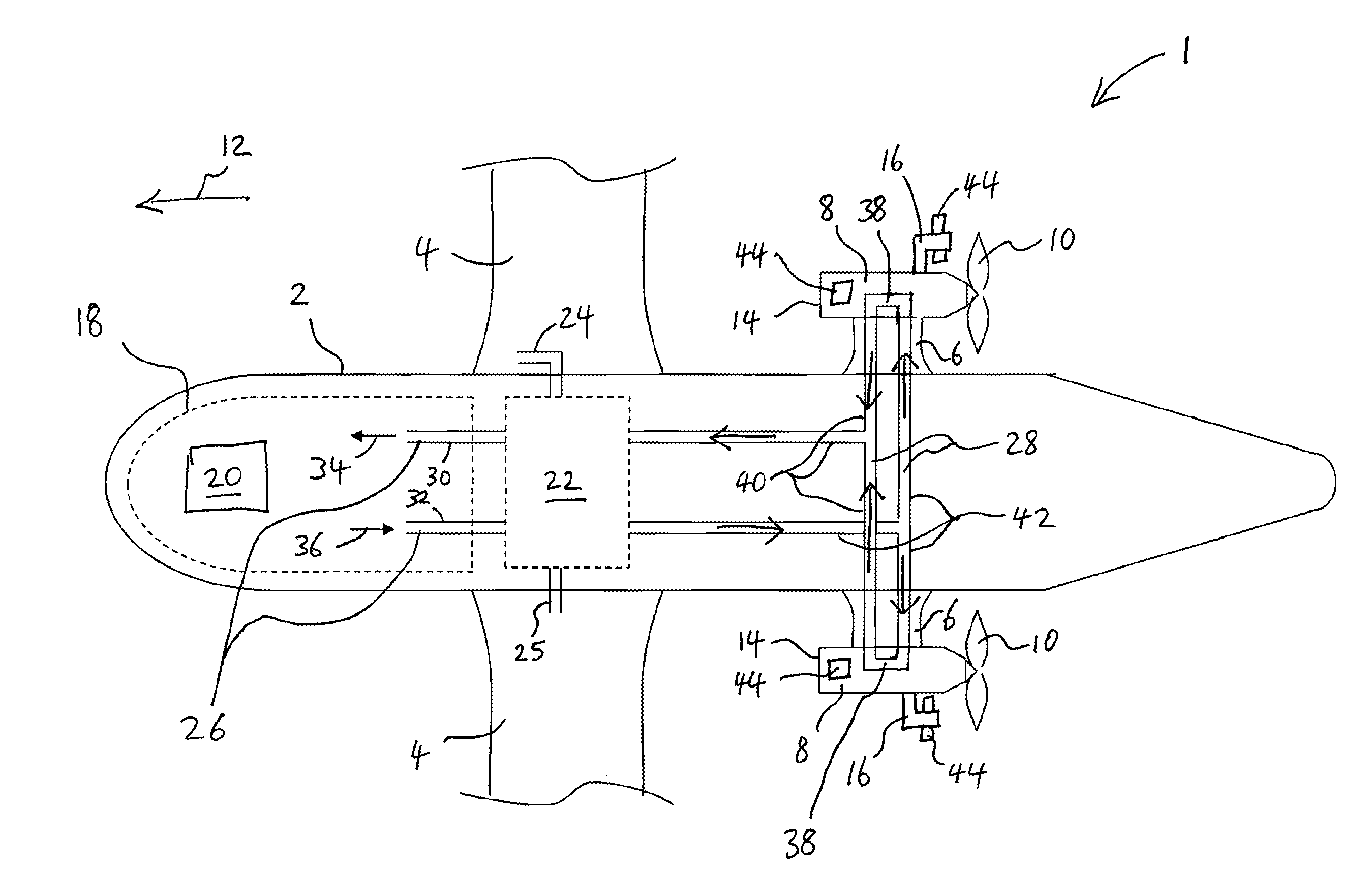
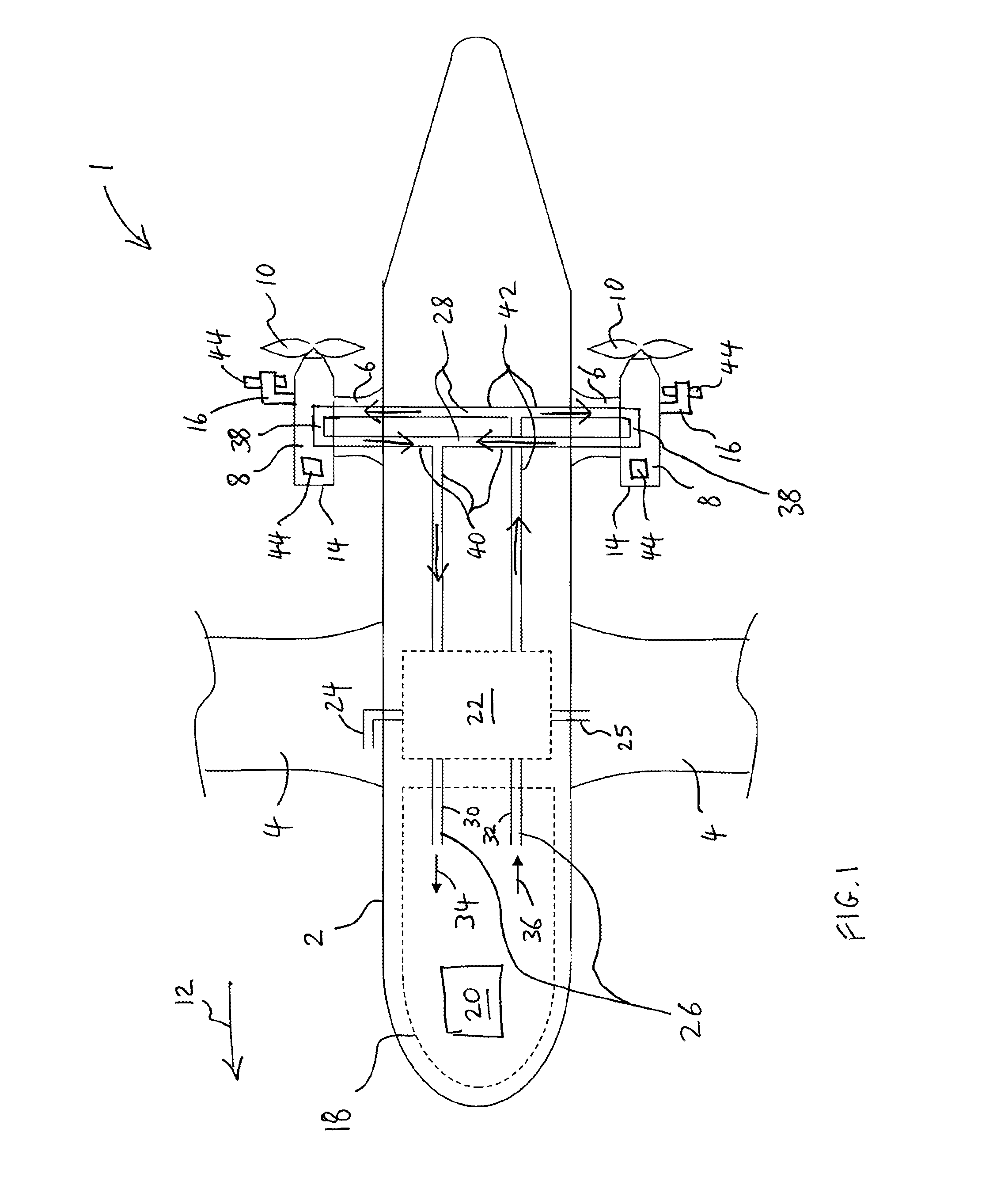
[0044]FIG. 1 is a schematic illustration (not to scale) of a turboprop-powered MALE aircraft 1 comprising a first embodiment of a thermal management system.

[0045]The turboprop-powered MALE aircraft 1 comprises a fuselage 2, wings 4 and engine support pylons 6.

[0046]Gas turbine engines 8, coupled to propellers 10, are attached to the engine support pylons 6. The gas turbine engines 8 drive the propellers 10 to provide propulsion to make the turboprop-powered MALE aircraft 1 travel in a flight direction 12. Each gas turbine engine 8 is encased in an engine casing 14, which itself is encased in a nacelle (not shown). Each gas turbine engine 8 has one or more exhaust ducts 16 (for clarity, in FIG. 1 only one exhaust duct 16 is shown for each gas turbine engine 8).

[0047]The turboprop-powered MALE aircraft 1 further comprises an equipment bay 18, which will typically carry a payload 20. The payload 20 may comprise one or more of surveillance equipment, navigation equipment, communications...


PUM


Abstract

A turboprop-powered medium altitude long endurance aircraft, having a gas turbine engine; a heat scavenging device to scavenge heat from the gas turbine engine; and a heating device to use the scavenged heat to provide heating to the aircraft. The heat scavenging device may be placed on an engine casing and / or on or in an engine exhaust duct. The heating device may include a circulation path routed directly to a location in the aircraft where heating is to be performed, for example a leading edge of an engine support pylon or a leading edge of an engine-carrying wing. The heating device can include a heat exchanger.

Description

FIELD OF THE INVENTION[0001]The present invention relates to thermal management of a turboprop aircraft, in particular a turboprop-powered Medium Altitude Long Endurance (MALE) aircraft.BACKGROUND[0002]For aircraft in general, many types of thermal management arrangements are known.[0003]On the one hand, many types of aircraft and / or aircraft mission profiles are relatively simple, for example light aircraft with piston-powered propellers flying at low speeds at low altitude, and the thermal management arrangements may accordingly be relatively undemanding, e.g. use of simple ram air may suffice.[0004]On the other hand, many other types of aircraft and / or aircraft mission profiles have highly demanding thermal management requirements, but factors such as the cost and complexity of those aircraft, and / or the high availability of fuel driven power during flight, make providing correspondingly complex and expensive (in terms of money or power consumption) thermal management arrangement...

Claims


Application Information

Patent Timeline
IPC IPC(8): F02C7/24
CPCF02C7/24B64D15/04B64D27/10B64D33/08B64D2013/0607B64D2013/0614B64D2013/0648B64D2013/0674F28F13/003F28D2020/0013F28D2020/0017B64D15/02B64D13/08Y02T50/50B64U50/11B64U10/25B64U50/12B64U20/96B64U50/13B64C39/024
Inventor SMITH, STEPHEN JOHN RICHARDWATT, KIERAN JAMESWHITE, ANDREW CHARLES
Owner BAE SYSTEMS PLC
Learn More