
Dielectric conduits for ehf communications

a dielectric conduit and ehf communication technology, applied in the field of devices, systems and methods for ehf communication, can solve problems such as discontinuities, expensive electronics to negotiate, and degradation of signal quality or integrity

Inactive Publication Date: 2013-10-24
KIM YANGHYO +4
View PDF6 Cites 59 Cited by
  • Summary
  • Abstract
  • Description
  • Claims
  • Application Information

AI Technical Summary

Benefits of technology

The invention is a new type of conduit for transmitting electromagnetic signals in the EHF range. The conduit has a unique design with dielectric material that allows for the proper propagation of these signals. The conduit has elongate bodies that are covered by a reflective cladding, which helps to further enhance the transmission of the signals. The method of use involves placing the end of the conduit near the signal source and allowing the signal to propagate through the conduit to the other end. The technical effects of this invention include improved signal transmission and enhanced stability and reliability of the signal during transmission.

Problems solved by technology

Unfortunately, such connector and backplane architectures introduce a variety of impedance discontinuities into the signal path, resulting in a degradation of signal quality or integrity.
Connecting to boards by conventional means, such as signal-carrying mechanical connectors, generally creates discontinuities, requiring expensive electronics to negotiate.
Conventional mechanical connectors may also wear out over time, require precise alignment and manufacturing methods, and are susceptible to mechanical jostling.
These characteristics of conventional connectors can lead to degradation of signal integrity and instability of electronic systems needing to transfer data at very high rates, which in turn limits the utility of such products.
The detrimental characteristics of conventional connectors lead to degradation of signal integrity and corresponding instability of electronic systems that are designed to transfer data at very high rates, which in turn limits the utility of such systems.

Method used


Image

  • Dielectric conduits for ehf communications
  • Dielectric conduits for ehf communications
  • Dielectric conduits for ehf communications

Examples


Embodiment Construction

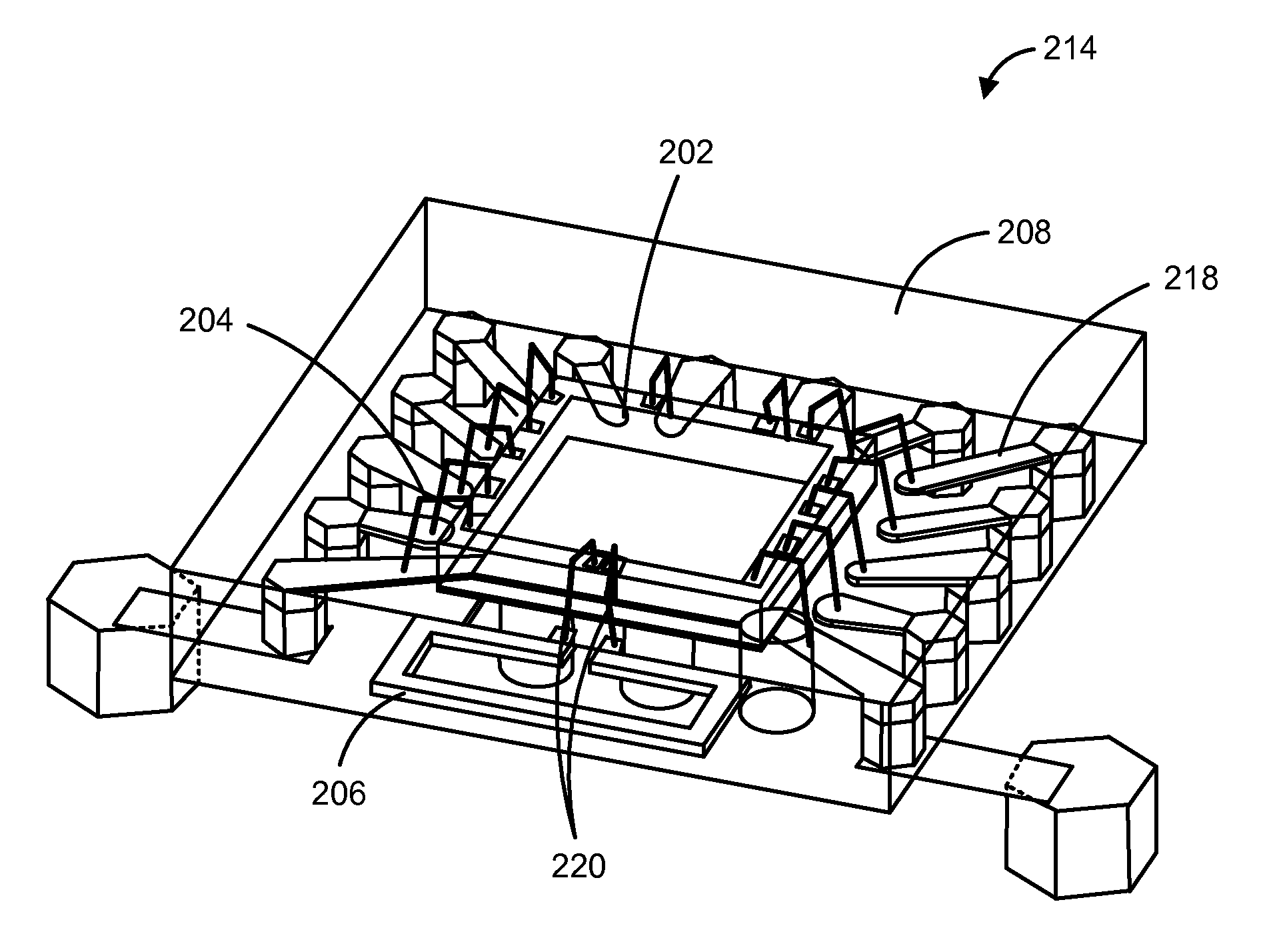
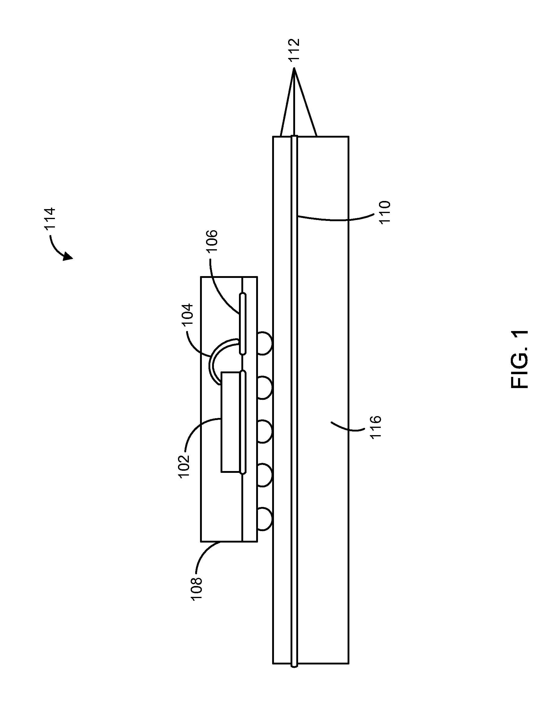
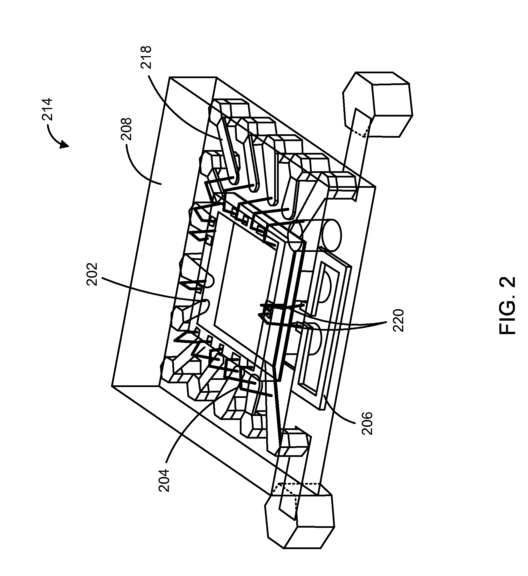
[0031]In the following description, numerous specific details are set forth to provide a thorough understanding of the present disclosure. Reference will be made to certain embodiments of the disclosed subject matter, examples of which are illustrated in the accompanying drawings. While the disclosed subject matter will be described in conjunction with the embodiments, it will be understood that it is not intended to limit the disclosed subject matter to these particular embodiments alone. On the contrary, the disclosed subject matter is intended to cover alternatives, modifications and equivalents that are within the spirit and scope of the disclosed subject matter as defined by the appended claims. In other instances, well known process steps have not been described in detail in order to avoid unnecessarily obscuring the present disclosure.

[0032]Moreover, in the following description, numerous specific details are set forth to provide a thorough understanding of the presently disc...


PUM


Abstract

Dielectric conduits for the propagation of electromagnetic EHF signals include an elongate body of a dielectric material extending continuously along a longitudinal axis between a first terminus and a second terminus. At each point along the longitudinal axis, an orthogonal cross-section of the elongate body has a first dimension along a major axis of the cross-section, where the major axis extends along the largest dimension of the cross-section. The orthogonal cross-section also has a second dimension along a minor axis of the cross-section, where the minor axis extends along a widest dimension of the cross-section that is at a right angle to the major axis. For each cross-section of the elongate body, the first dimension is greater than the wavelength of the electromagnetic EHF signals and the second dimension is less than the wavelength of the electromagnetic EHF signals.

Description

RELATED PATENTS AND APPLICATIONS[0001]This application claims the benefit under 35 U.S.C. §119(e) of U.S. Provisional Patent Application No. 61 / 661,756, filed Jun. 19, 2012, and entitled DIELECTRIC COUPLERS FOR EHF COMMUNICATIONS, which application is incorporated herein by reference in its entirety for all purposes.[0002]The present application is a continuation-in-part under 35 U.S.C. §120 of U.S. patent application Ser. No. 13 / 541,543, filed Jul. 3, 2012, and entitled EHF COMMUNICATION WITH ELECTRICAL ISOLATION AND WITH DIELECTRIC TRANSMISSION MEDIUM; which in turn claims the benefit under 35 U.S.C. §119(e) of U.S. Provisional Patent Application No. 61 / 504,625, filed Jul. 5, 2011 and entitled ELECTRICAL ISOLATOR USING EHF COUPLING, each of which is incorporated by reference in its entirety.[0003]The present application is also a continuation under 35 U.S.C. §120 of the following: (1) U.S. patent application Ser. No. 13 / 760,089, filed Feb. 6, 2013 and entitled CONTACTLESS REPLACEM...

Claims


Application Information

Patent Timeline
IPC IPC(8): H01P3/16
CPCH04B5/0031H04B5/02H01L2924/3025H01L2924/3011H01P3/165H01L2924/15311H01L2224/73265H01L2224/48227H01L2224/32225H01L2223/6677H01L2924/00012H01L2924/00H01L24/73H04B5/72H04B5/48
Inventor KIM, YANGHYOCHANG, MAU-CHUNG FRANKSOVERO, EMILIOMCCORMACK, GARY D.KYLES, IAN A.
Owner KIM YANGHYO
Learn More