
Systems and methods for superconducting flux qubit readout

a superconducting quantum processor and readout system technology, applied in the direction of pulse technique, logic circuit, instruments, etc., can solve the problems of real implementation the heating effect of the readout system b>200/b> can still be problematic, and the time it takes to produce a satisfactory solution to the computational problem is considerably increased

Active Publication Date: 2013-10-24
D WAVE SYSTEMS INC
View PDF3 Cites 26 Cited by
  • Summary
  • Abstract
  • Description
  • Claims
  • Application Information

AI Technical Summary

Benefits of technology

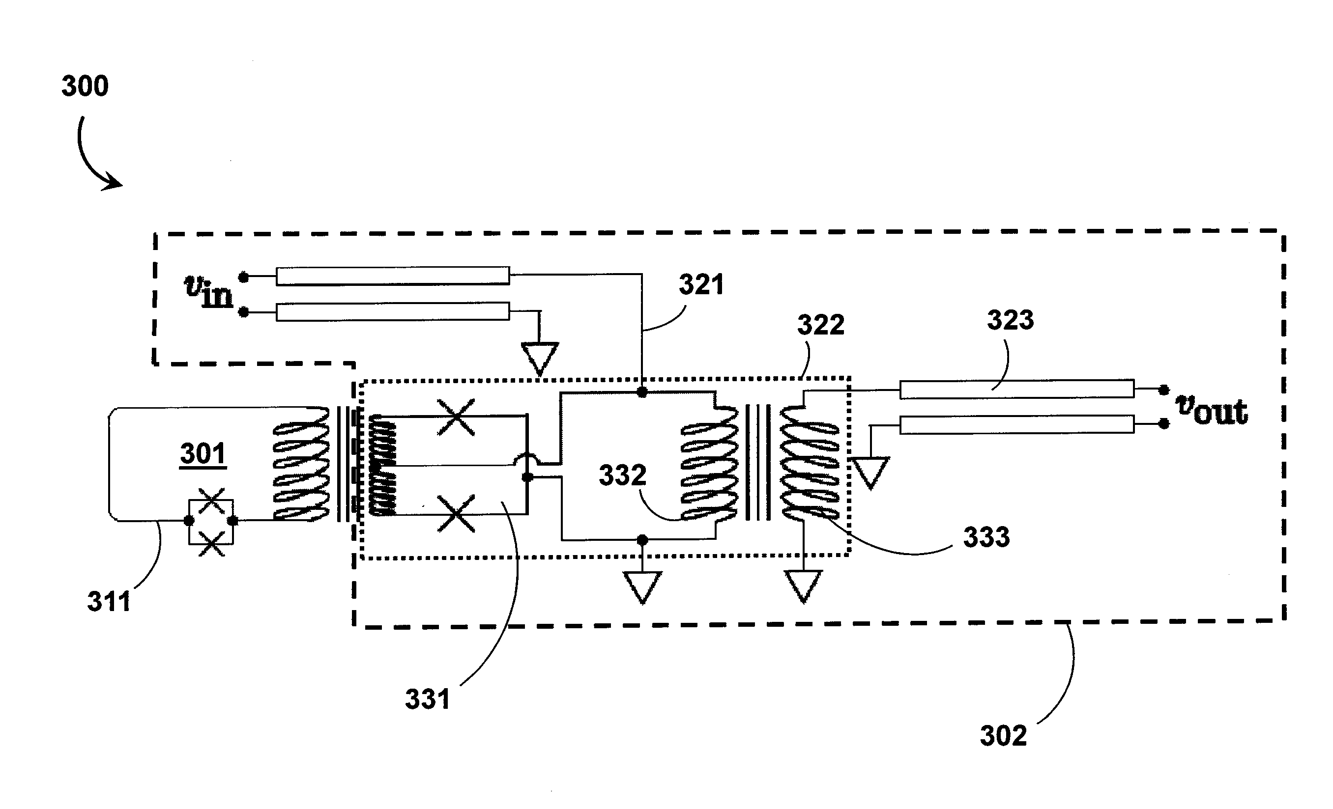
The patent describes a system for reading the state of a superconducting flux qubit using a DC-SQUID and a Josephson junction. The system includes a first superconducting flux qubit and a first latching qubit, which are connected to each other through a Josephson junction. The system also includes a second superconducting flux qubit and a second latching qubit, which are connected to the first qubit through a Josephson junction. The system can also include additional latching qubits and a plurality of additional latching qubits. The system uses a time-varying drive current to induce a current in the Josephson junctions, which is then transmitted through the signal output line. The system can determine the state of the superconducting flux qubit based on the characteristics of the output signal.

Problems solved by technology

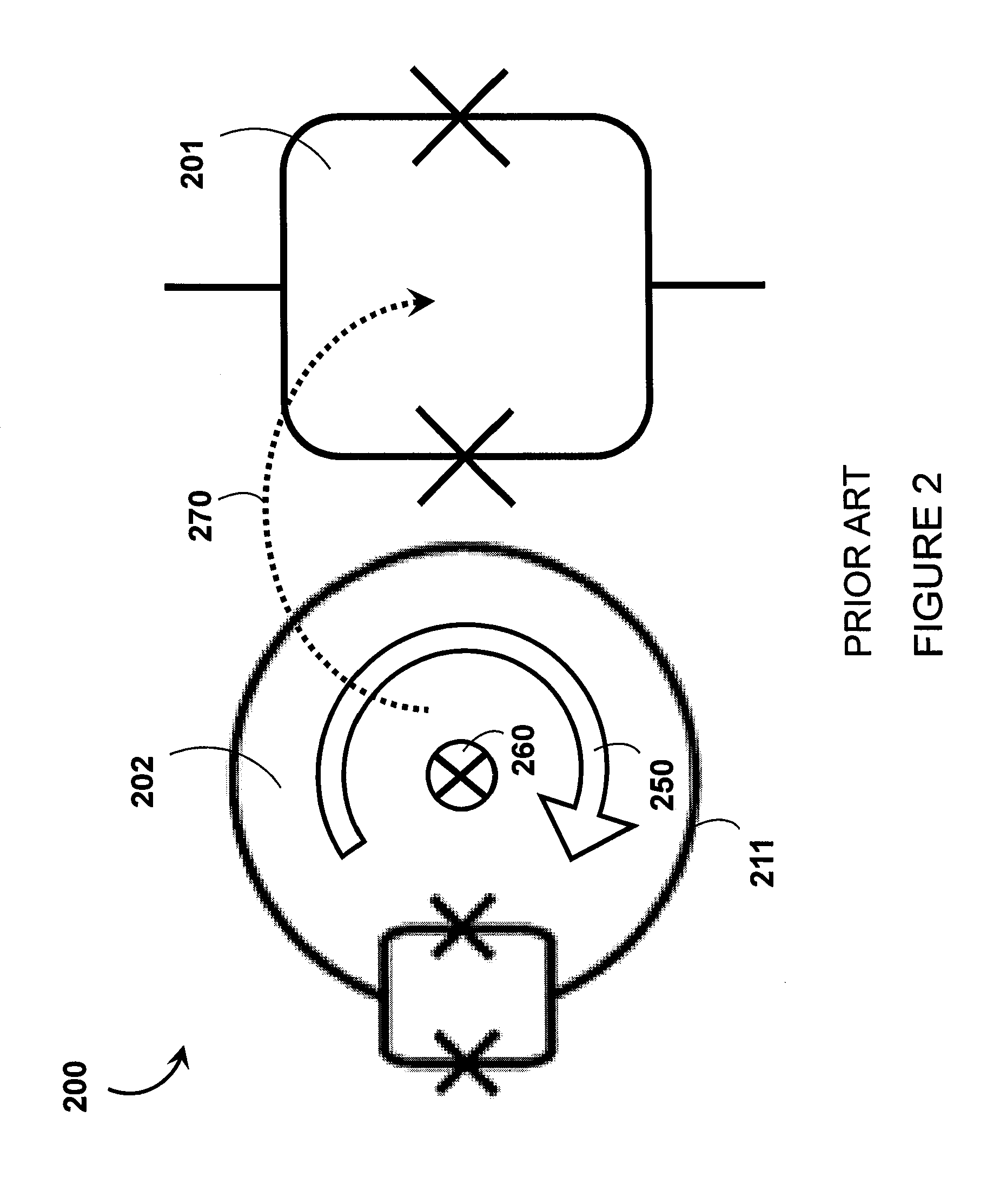
Nonetheless, real implementations of readout system 200 can be problematic because a readout event can involve the dissipation of significant energy.
For a single computation there are no further evolutions of the qubits required after readout, but the heating effects of readout system 200 can still be problematic.
Depending on the cooling power of the refrigeration system being used and on the quality of thermal connections to the qubits, the resulting thermalization delays can considerably increase the time it takes to produce a satisfactory solution to the computational problem.

Method used


Image

  • Systems and methods for superconducting flux qubit readout
  • Systems and methods for superconducting flux qubit readout
  • Systems and methods for superconducting flux qubit readout

Examples


Embodiment Construction

[0038]In the following description, some specific details are included to provide a thorough understanding of various disclosed embodiments. One skilled in the relevant art, however, will recognize that embodiments may be practiced without one or more of these specific details, or with other methods, components, materials, etc. In other instances, well-known structures associated with quantum processors, such as quantum devices, coupling devices, and control systems including microprocessors and drive circuitry have not been shown or described in detail to avoid unnecessarily obscuring descriptions of the embodiments of the present systems and methods. Throughout this specification and the appended claims, the words “element” and “elements” are used to encompass, but are not limited to, all such structures, systems and devices associated with quantum processors, as well as their related programmable parameters.

[0039]Unless the context requires otherwise, throughout the specification...


PUM


Abstract

Systems and methods for reading out the states of superconducting flux qubits may couple magnetic flux representative of a qubit state to a DC-SQUID in a variable transformer circuit. The DC-SQUID is electrically coupled in parallel with a primary inductor such that a time-varying (e.g., AC) drive current is divided between the DC-SQUID and the primary inductor in a ratio that is dependent on the qubit state. The primary inductor is inductively coupled to a secondary inductor to provide a time-varying (e.g., AC) output signal indicative of the qubit state without causing the DC-SQUID to switch into a voltage state. Coupling between the superconducting flux qubit and the DC-SQUID may be mediated by a routing system including a plurality of latching qubits. Multiple superconducting flux qubits may be coupled to the same routing system so that a single variable transformer circuit may be used to measure the states of multiple qubits.

Description

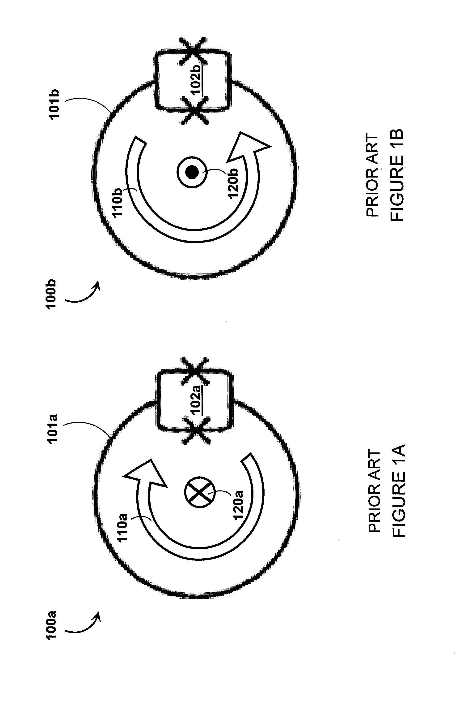
CROSS REFERENCE TO RELATED APPLICATIONS[0001]This application claims benefit under 35 U.S.C. 119(e) of U.S. Provisional Patent Application Ser. No. 61 / 412,691, filed Nov. 11, 2010, and entitled “Systems And Methods for Superconducting Flux Qubit Readout,” which is incorporated herein by reference in its entirety.BACKGROUNDField[0002]The present systems and methods generally relate to readout schemes for superconducting quantum processors implementing superconducting flux qubits.Superconducting Qubits[0003]There are many different hardware and software approaches under consideration for use in quantum computers. One hardware approach employs integrated circuits formed of superconducting material, such as aluminum and / or niobium, to define superconducting qubits. Superconducting qubits can be separated into several categories depending on the physical property used to encode information. For example, they may be separated into charge, flux and phase devices. Charge devices store and m...

Claims


Application Information

Patent Timeline
Patent Type & Authority Applications(United States)
IPC IPC(8): H03K19/195
CPCH03K19/195B82Y10/00G06N10/00
Inventor BERKLEY, ANDREW J.
Owner D WAVE SYSTEMS INC
Learn More