
Valve Combined With Water Hammer Arrester

a technology of valves and arresters, applied in the direction of valve details, valve arrangements, valve members for absorbing fluid energy, etc., can solve the problems of increased manufacturing costs, accompanies some problems, and damage to pipes, so as to save personnel costs and reduce the volume of valves

Inactive Publication Date: 2013-10-17
ASIA UNION +1
View PDF8 Cites 24 Cited by
  • Summary
  • Abstract
  • Description
  • Claims
  • Application Information

AI Technical Summary

Benefits of technology

The present invention provides a valve combined with a water hammer arrester, which avoids the need for additional parts like an intermediate connection member, a connection pipe, and a socket connection member. This saves money and simplifies the installation process. The combination valve performs the functions of multiple parts, including a water hammer arrester, and is compact in design. The valve is easy to install and use, and reduces the risk of leaks and other problems associated with traditional valves. Overall, the present invention provides a more efficient, cost-effective, and reliable solution for preventing water hammer in valve systems.

Problems solved by technology

Generally, if the flow of a fluid like water on a pipe instantaneously stops, strong shock and noise occur in the pipe due to the inertia of the fluid to cause serious pipe damage.
Accordingly, the conventional structure wherein the valve is coupled to the water hammer arrester by using the angle valve or the specific connection member accompanies some problems.
So as to connect the water hammer arrester to the branch pipe of the intermediate connection member, further, the socket connection member should be welded to the insertion portion of the water hammer arrester, which raises additional manufacturing costs.

Method used


Image

  • Valve Combined With Water Hammer Arrester
  • Valve Combined With Water Hammer Arrester
  • Valve Combined With Water Hammer Arrester

Examples


first embodiment

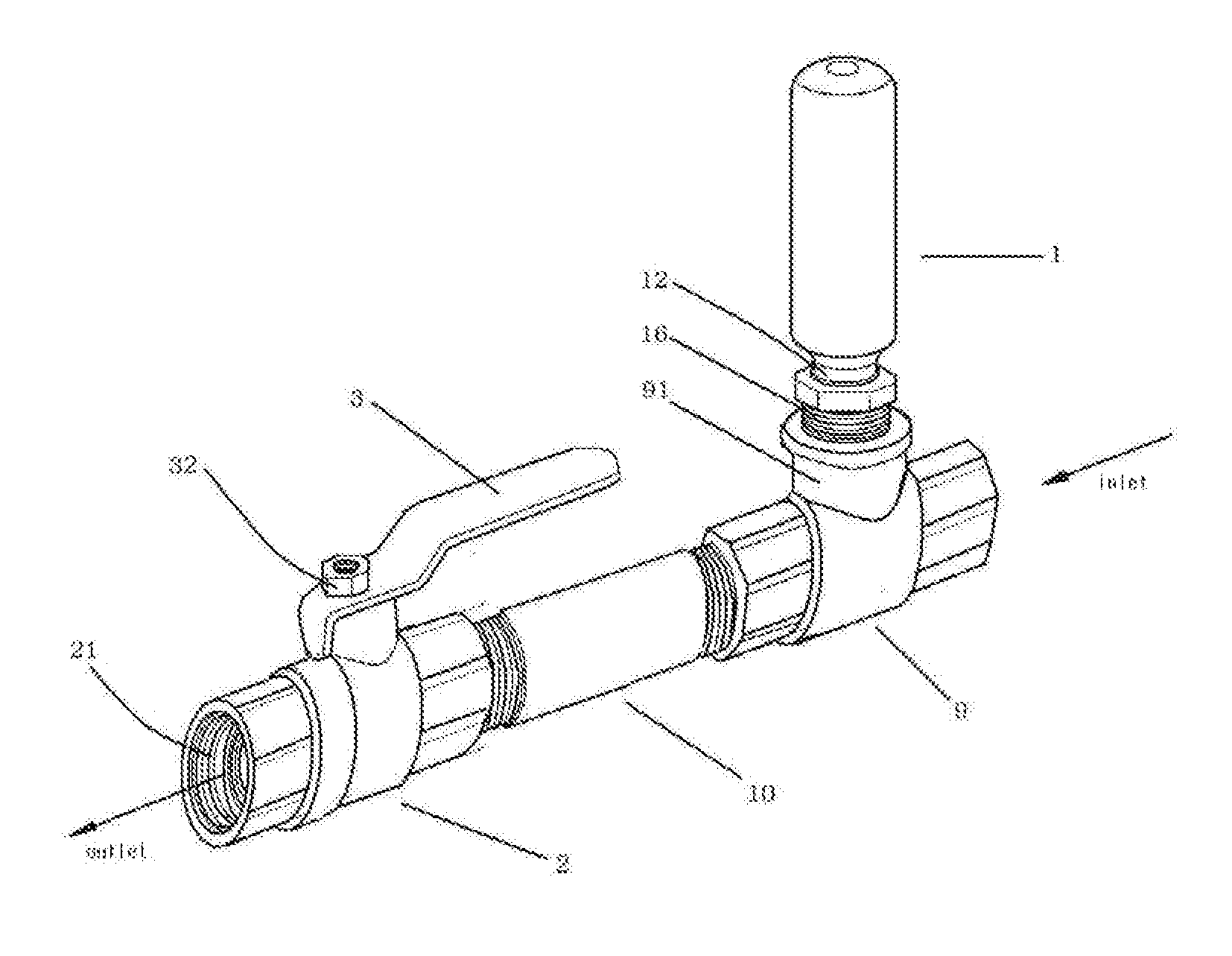
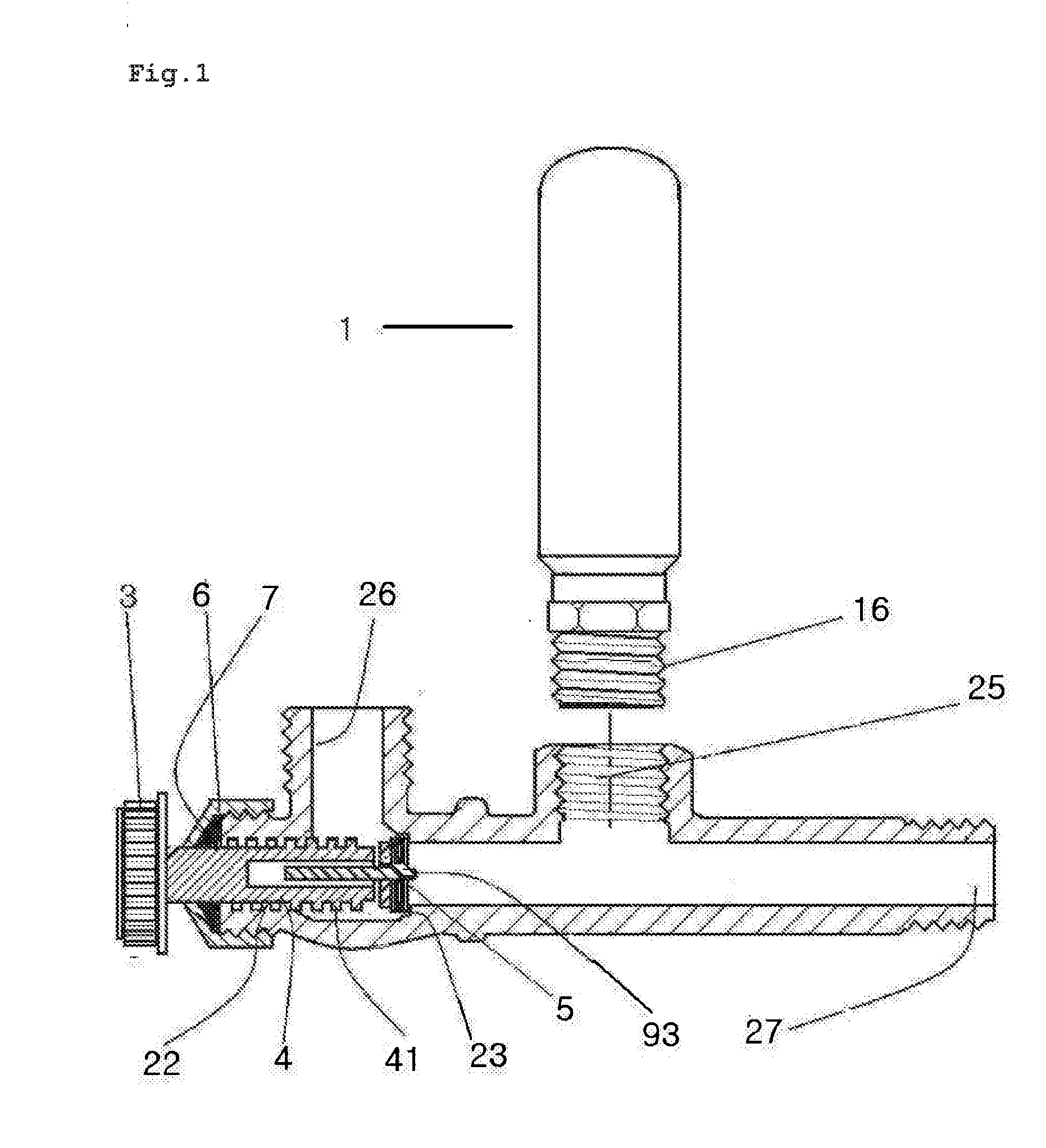
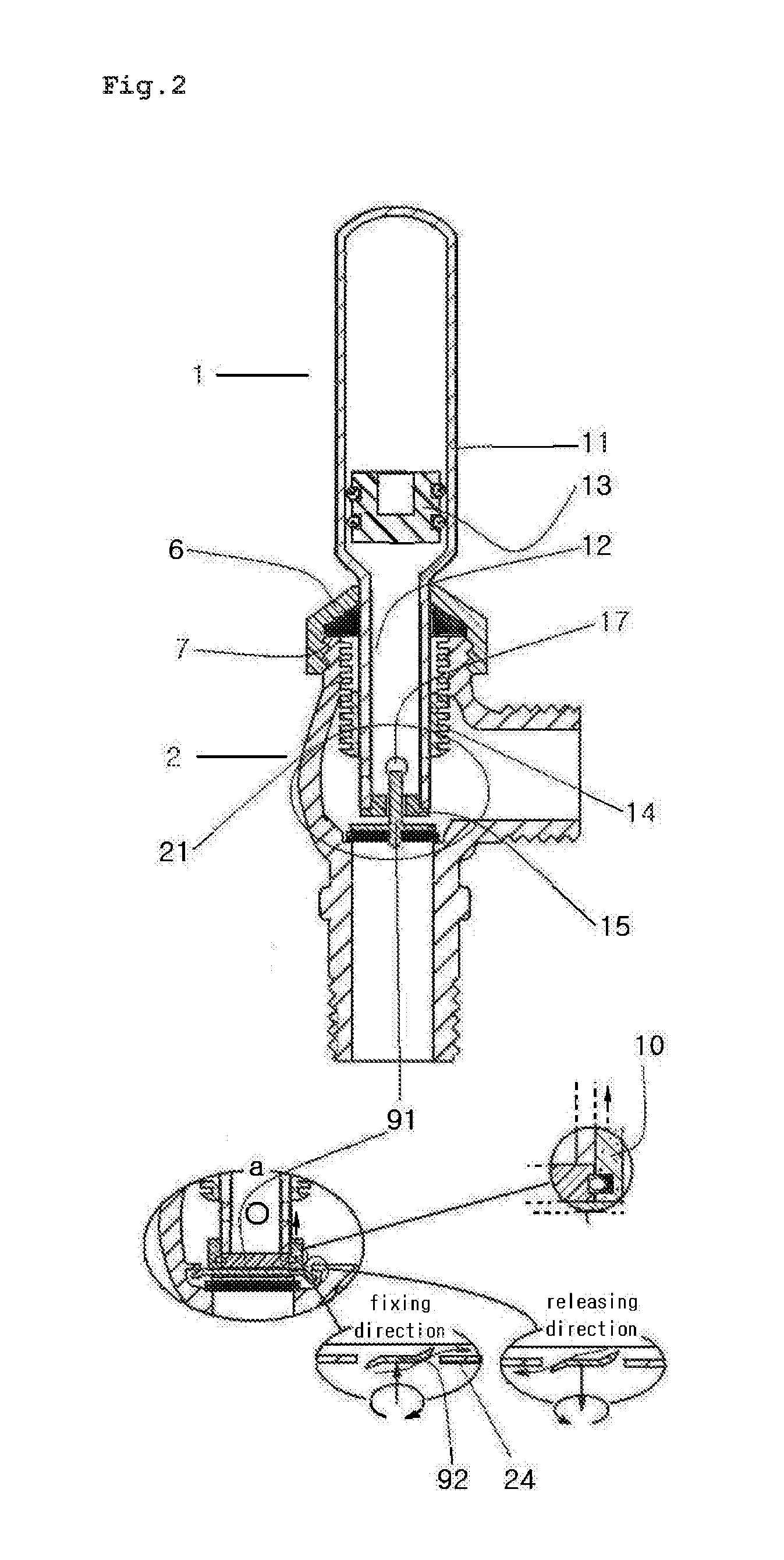
[0024]According to the present invention wherein if the body 11 of the water hammer arrester 1 serves as the handle of the valve, it is easy to manipulate the valve 2, which solves the conventional problem wherein so as to reduce the whole volume of the valve and the manufacturing cost thereof, the size of the conventional handle becomes small, thereby making the manipulation of the handle actually hard. In view of economical benefits, further, the lower portion of the water hammer arrester 1 is reduced to form the insertion portion 12 into which a given connection member is inserted, so that through simple machining and change, the insertion portion 12 can be replaced with the spindle of the conventional valve. Moreover, a fluid inlet port 18 (see FIG. 5) formed as a passage of a fluid on the lower end of the water hammer arrester 1 is utilized as a space into which a stem 93 of a conventional shutoff part 5 as shown in FIG. 1 is inserted, and in this case, if the size of the space...

second embodiment

[0026]According to the present invention, as shown in FIG. 3, the shutoff part 5 of the ball valve is configured in a simple manner to have a ball embedded into the body 21 of the valve and a packing inserted into a gap between the body 21 and the ball. Accordingly, the insertion portion 12 of the water hammer arrester 1 is coupled with the ball as the shutoff part, and so as to transmit a driving force to them, the insertion portion 12 and a fixing groove formed on the ball are welded or fixed to each other by means of fixing pins or screws 9. Alternatively, the insertion portion 12 of the water hammer arrester 1 and the fixing groove of the ball are coupled polygonally to each other. So as to prevent the body 21 of the valve and the insertion portion 12 of the water hammer arrester 1 from being escaped from each other or to prevent water between them from leaking to the outside, further, the shutoff part of the ball valve includes a packing, a fixing ring 8 adapted to be inserted ...

fourth embodiment

[0029]More particularly, if a side fluid inlet port 17 (as shown in FIG. 5) is formed on an appropriate position of the side portion of the insertion portion 12 forming the spindle of the water hammer arrester 1, the passage connected with the fluid inlet port of the insertion portion 12 has the same function as the passage of the ball of the ball valve. the present invention has the passage in a shape of “⊥” or “┤” like the ball or a large number of passages than the ball. Instead of the ball as an opening / closing part of the body of the valve, the insertion portion 12, which serves as the opening / closing member of the valve formed as the side fluid passage, becomes the opening / closing part of the body of the valve. Accordingly, there is no large difference between the basic structures in coupling of the invention and the conventional practice, and the installation of other additional members in the invention is almost the same as the conventional practice. That is, a packing is di...


PUM


Abstract

The present invention relates to a valve combined with a water hammer arrester, including the water hammer arrester having a cylindrical casing having one side closed and the other side open, a shock-absorbing material being put into the cylindrical casing, and a piston adapted to be inserted into the cylindrical casing, the piston having packing members mounted thereon to prevent the leakage of the shock-absorbing material, wherein a drive part of the valve has an insertion portion formed by reducing the lower portion of the water hammer arrester, so that the insertion portion of the water hammer arrester functions as a spindle of the valve and a body of the water hammer arrester functions as an operating handle of the valve.

Description

CROSS-REFERENCE TO RELATED APPLICATIONS[0001]This application is based on and claims priority from Korean Patent Applications Nos. 10-2012-0038842 and 10-2012-0097221, filed Apr. 14, 2012 and Sep. 3, 2012 in the Korean Intellectual Property Office, the disclosures of which are incorporated herein by reference.BACKGROUND OF THE INVENTION[0002]1. Field of the Invention[0003]The present invention relates to a valve combined with a water hammer arrester, and more particularly, to a valve combined with a water hammer arrester wherein the valve connected horizontally on a pipe is coupled integrally to the water hammer arrester, unlike the conventional practice wherein the valve and the water hammer arrester are installed separably from each other.[0004]2. Description of Related Art[0005]Generally, if the flow of a fluid like water on a pipe instantaneously stops, strong shock and noise occur in the pipe due to the inertia of the fluid to cause serious pipe damage. So as to absorb such wat...

Claims


Application Information

Patent Timeline
Patent Type & Authority Applications(United States)
IPC IPC(8): F16L55/055
CPCF16L55/055F16K47/02F16L55/05F16L55/053
Inventor JANG, JAE IK
Owner ASIA UNION
Learn More