
Platform assembly for supporting cabinets

a platform and cabinet technology, applied in the field of cabinetry, can solve the problems of affecting the installation process of the cabinet installer, affecting the stability of the cabinet, and the length of the wooden platform is susceptible to damage, so as to achieve stable and durable, reduce the amount of wood product consumed and used in the cabinet installation process, and advantageously durable

Active Publication Date: 2013-10-10
ROYSTON HAMILTON LLC
View PDF8 Cites 1 Cited by
  • Summary
  • Abstract
  • Description
  • Claims
  • Application Information

AI Technical Summary

Benefits of technology

The present invention provides several advantages over traditional wooden platform assemblies. Metal platforms are more durable and stable, and they reduce the amount of wood used in cabinet installation. The metal toe-kick is also durable and helps with efficient placement and leveling of cabinets. The platform assembly is compatible with different types of floors and can be installed and leveled without the cabinets. It can be made to any desired size and can be sold in bulk or individually. The method of installing cabinets without measuring their positions also improves efficiency and ease of installation.

Problems solved by technology

Such attachments can be difficult, especially at the back side of the cabinets, which is often positioned adjacent a wall.
This is typically accomplished by measuring and registrating the cabinets relative to the supporting platform which is oftentimes prone to error and complicates the installation process for the cabinet installer.
Moreover, in separate wood platforms, the lengths of wood making up the wooden platform are susceptible to changes caused by environmental conditions, such as temperature and humidity, and these changes are not necessarily predictable or desirable.

Method used


Image

  • Platform assembly for supporting cabinets
  • Platform assembly for supporting cabinets
  • Platform assembly for supporting cabinets

Examples


Embodiment Construction

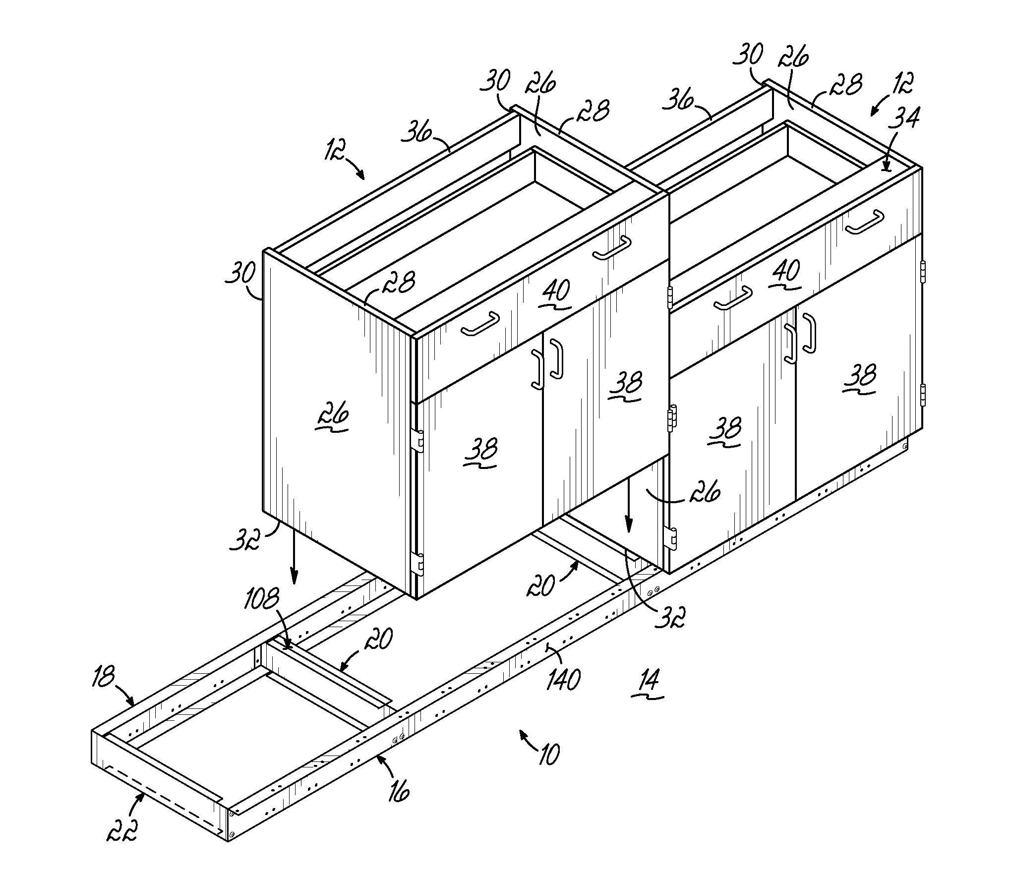
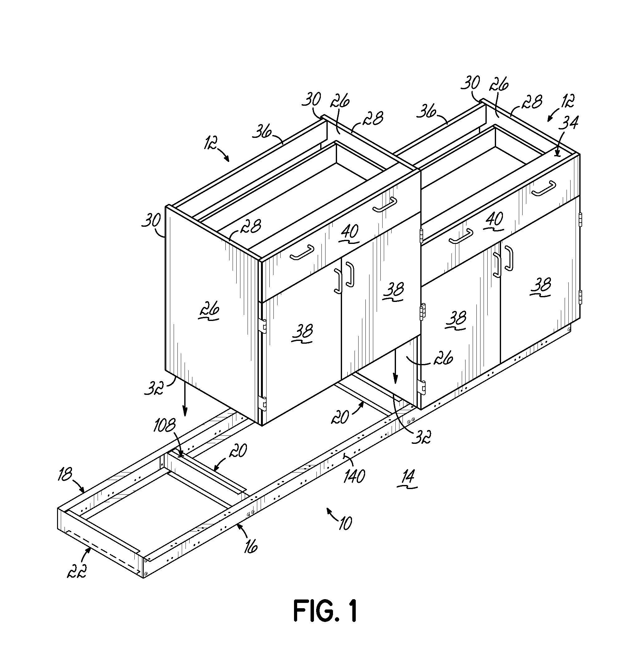
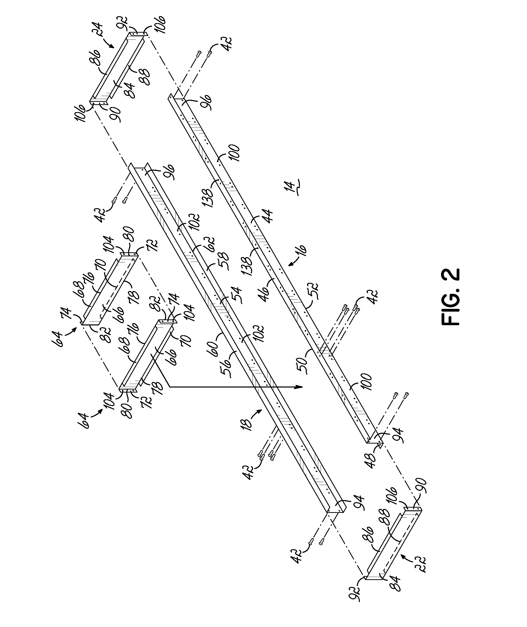
[0023]Referring now to the figures, FIG. 1 illustrates a platform assembly 10 according to one embodiment for supporting one or more cabinets 12 above a floor surface 14. As will be described in greater detail below, the platform assembly 10 may be made of metal, such as steel, for supporting cabinets 12 which may be made of any suitable material. The platform assembly 10 generally includes a front rail 16, a rear rail 18, connector rails 20, and a pair of end rails 22, 24 (end rail 24 being visible in FIGS. 2-4).

[0024]In the embodiment shown, each cabinet 12 includes opposed side panels 26, with each side panel 26 having an upper edge 28, a rear edge 30, and a lower edge 32. The upper edges 28 of the cabinets 12 define a worktop support surface 34 for supporting a work surface (not shown) to be installed on the cabinets 12. The lower edges 32 are configured for at least partially supporting the cabinets 12 on the platform assembly 10. A fastening rail 36 extends between opposed sid...


PUM

PropertyMeasurementUnit
shapeaaaaaaaaaa
z-shapeaaaaaaaaaa
heightaaaaaaaaaa

Abstract

A platform assembly for supporting one or more cabinets includes a first rail having a generally z-shape in cross-section, a second rail having a generally c-shape in cross-section and extending generally parallel to the first rail, and a plurality of connector rails coupled to and extending generally transverse to the first and second rails. End rails are also coupled to respective terminal ends of the first and second rails. The first and second rails are made of metal so that at least the first rail provides a metal toe-kick below the one or more cabinets.

Description

[0001]The present application claims the filing benefit of U.S. Provisional Application Ser. No. 61 / 621,748, filed Apr. 9, 2012, the disclosure of which is hereby incorporated herein by reference in its entirety.FIELD OF THE INVENTION[0002]The present invention relates generally to cabinetry and, more particularly, to platform assemblies upon which cabinets are supported and leveled, as well as related methods.BACKGROUND OF THE INVENTION[0003]Typically, cabinets installed on a floor surface include a supporting platform or base, which may be separate or integral with the cabinets. The platform or base is provided to level and support the cabinets at an appropriate height, including any work surface supported thereon.[0004]For example, a wooden platform made of several interconnected lengths of wood can be installed and leveled on a floor surface, and cabinets can thereafter be installed on the wooden platform. Typically, the cabinets are fastened to the wooden platform with screws o...

Claims


Application Information

Patent Timeline
Patent Type & Authority Applications(United States)
IPC IPC(8): A47B91/00B23P11/00A47B96/00
CPCY10T29/49959A47B91/005
Inventor SEEFELDT, DAVID A.NIGBOR, JOSHUA D.ANSORGE, DAVID A.
Owner ROYSTON HAMILTON LLC
Learn More