
Vehicular air conditioner and assembly method therefor

a technology for vehicles and air conditioners, applied in vehicle heating/cooling devices, transportation and packaging, manufacturing tools, etc., can solve the problems of deterioration in assembly ease and difficulty in assembly to be carried out with good efficiency, and achieve the improvement of assembly ease with respect to cases, the effect of increasing the weight of the apparatus and deteriorating the assembly eas

Inactive Publication Date: 2013-10-03
KEIHIN CORP
View PDF2 Cites 10 Cited by
  • Summary
  • Abstract
  • Description
  • Claims
  • Application Information

AI Technical Summary

Benefits of technology

The present invention provides a simple structure for assembling a slide damper in a vehicular air conditioner having a divided casing configuration. The invention prevents the door main body from falling over and corrects any inclination to a proper position, allowing for easy assembly of the other casing without the need for additional parts or supporting device. The technical effects include improved assembly efficiency and reliability.

Problems solved by technology

However, for example, in the event that the slide damper device according to the aforementioned Patent Document 1 is applied to a vehicular air conditioner having two divided casings, in a condition in which the slide damper is assembled into one of the divided casings, although the other divided casing can be assembled thereon, it is difficult for assembly to be carried out with good efficiency due to backlash or jostling of the slide damper.
Further, in the case that a slidably displaceable mixing door main body is assembled with respect to a pair of divided casings, as in the vehicular air conditioner of the aforementioned Patent Document 2, in a state in which the mixing door main body is assembled on one of the divided casings, it becomes difficult to assemble the other divided casing thereon, leading to a deterioration in the ease of assembly thereof.

Method used


Image

  • Vehicular air conditioner and assembly method therefor
  • Vehicular air conditioner and assembly method therefor
  • Vehicular air conditioner and assembly method therefor

Examples


Embodiment Construction

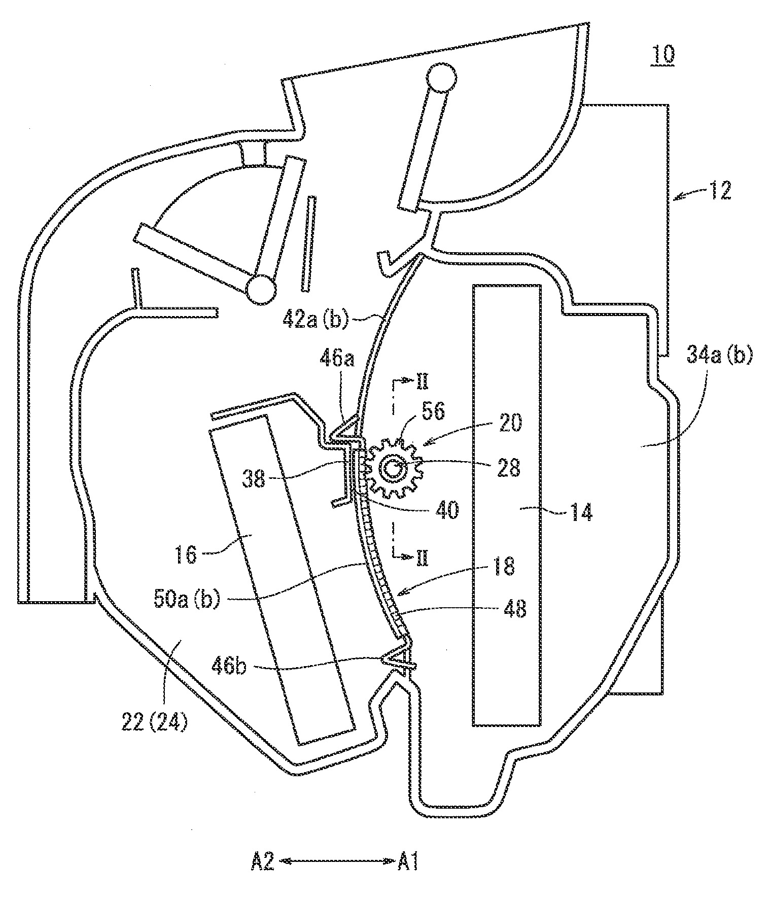
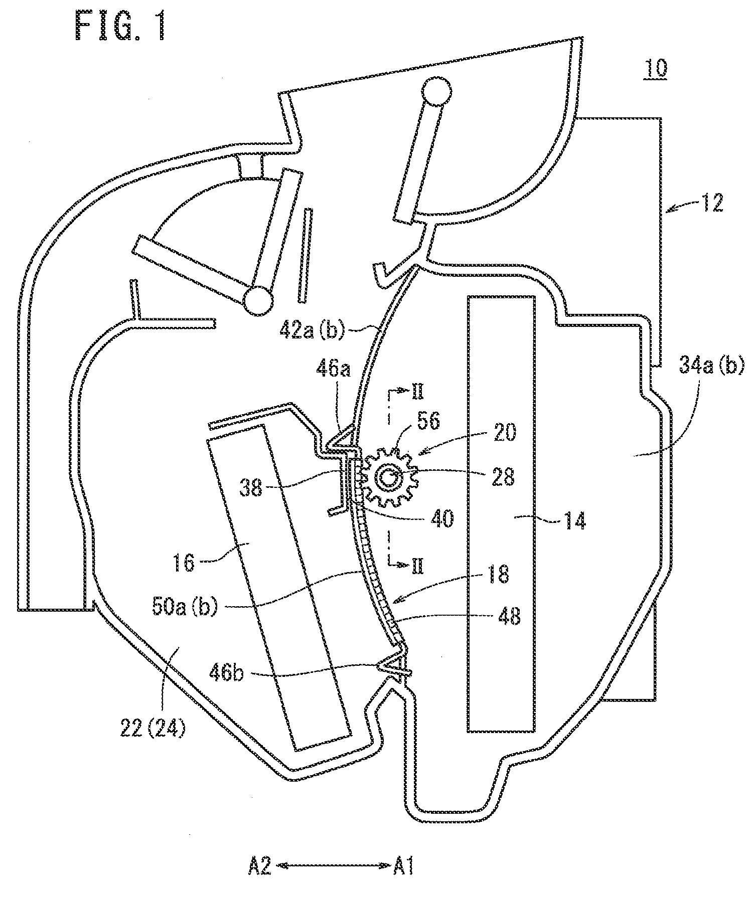
[0027]As shown in FIG. 1, a vehicular air conditioner 10 includes a casing 12 that makes up respective air flow passages, an evaporator 14 arranged in the interior of the casing 12 for cooling air, a heater core 16 for heating the air, an air mixing damper (slide mechanism, slide damper) 18 by which heat exchange is carried out by the evaporator 14 and the heater core 16 on air that is directed into the interior of the casing 12, and which creates mixed air by mixing at a predetermined mixing ratio cool air and heated air that have been adjusted in temperature, and a driving force transmission mechanism 20 that transfers a driving force of a drive source (not shown) disposed on a side surface of the casing 12 to the air mixing damper 18 for effecting rotary displacement thereon.

[0028]The casing 12 is made up of first and second substantially symmetrically shaped divided casings 22 and 24. In an opening, which opens on a side portion of the first divided casing 22, a duct (not shown)...


PUM

PropertyMeasurementUnit
displacementaaaaaaaaaa
movementaaaaaaaaaa
heightaaaaaaaaaa

Abstract

An air mixing damper, which is displaceable in a direction substantially perpendicular to an air flow direction, is disposed between an evaporator and a heater core in a casing that constitutes a vehicular air conditioner. In the air mixing damper, a plurality of ribs are formed so as to project on a side of a dividing wall that divides an air flow passage, and rack gears, which are enmeshed with a shaft, are formed on an inner circumferential surface on the opposite side thereof. In addition, when the air mixing damper is assembled in the casing, in a condition in which the ribs are in abutment against a sealing surface of the dividing wall, pinion gears of the shaft are enmeshed with the rack gears, whereby jostling of the air mixing damper is prevented.

Description

CROSS-REFERENCE TO RELATED APPLICATION[0001]This application is based upon and claims the benefit of priority from Japanese Patent Application No. 2012-070914 filed on Mar. 27, 2012, the contents of which are incorporated herein by reference.BACKGROUND OF THE INVENTION[0002]1. Field of the Invention[0003]The present invention relates to a vehicular air conditioner, which is mounted in a vehicle, and by which air, which has been adjusted in temperature by a heat exchanger, is blown into a vehicle cabin to thereby carry out air conditioning inside the vehicle cabin. The present invention also concerns an assembly method for such a vehicular air conditioner.[0004]2. Description of the Related Art[0005]Heretofore, a vehicular air conditioner, which is installed in a vehicle, takes in interior and exterior air by a fan into an air flow passage formed in an interior portion of a casing, and after mixing chilled air, which is cooled by an evaporator type of cooling means, and heated air, w...

Claims


Application Information

Patent Timeline
Patent Type & Authority Applications(United States)
IPC IPC(8): B60H1/00
CPCB60H1/00457B60H1/00692B60H2001/00714Y10T29/49826
Inventor KAIYAMA, KOICHITAKAHASHI, HIROHARUITO, YOSHIOMI
Owner KEIHIN CORP
Learn More