
Projection type display device, display system, and display method

a display device and projection technology, applied in the field of projection display devices, display systems, display methods, etc., can solve the problems of user not being able to recognize the occurrence of errors and not being able to recognize errors

Inactive Publication Date: 2013-10-03
SEIKO EPSON CORP
View PDF3 Cites 4 Cited by
  • Summary
  • Abstract
  • Description
  • Claims
  • Application Information

AI Technical Summary

Benefits of technology

The invention provides a system for displaying images using multiple projection type display devices. The technical effect of this system is that it can reliably notify the user when an error occurs in a certain display device. This is achieved by separately displaying the first and second images without overlapping each other, ensuring that the content displayed in each image can be reliably transmitted to the user. Additionally, when only the brightness of the displayed image is changed due to an error, the user can be reliably notified of the error.

Problems solved by technology

When displaying an image using this method, even if an error occurs in a certain projection type display device and accordingly a corresponding image is no longer displayed, the user may not notice the occurrence of an error since the brightness of the displayed image is only reduced.
In this case, even if the projection type display device notifies the user of the occurrence of an error by turning on an LED (Light Emitting Diode), the user may not recognize the occurrence of the error if the user does not know the meaning of the LED lighting.
In addition, in this technique, it is not possible to recognize the occurrence of an error unless the user has a device that displays an e-mail and notices the arrival of the e-mail.

Method used


Image

  • Projection type display device, display system, and display method
  • Projection type display device, display system, and display method
  • Projection type display device, display system, and display method

Examples


embodiments

[0044]Hereinafter, embodiments of the invention will be described with reference to the accompanying drawings.

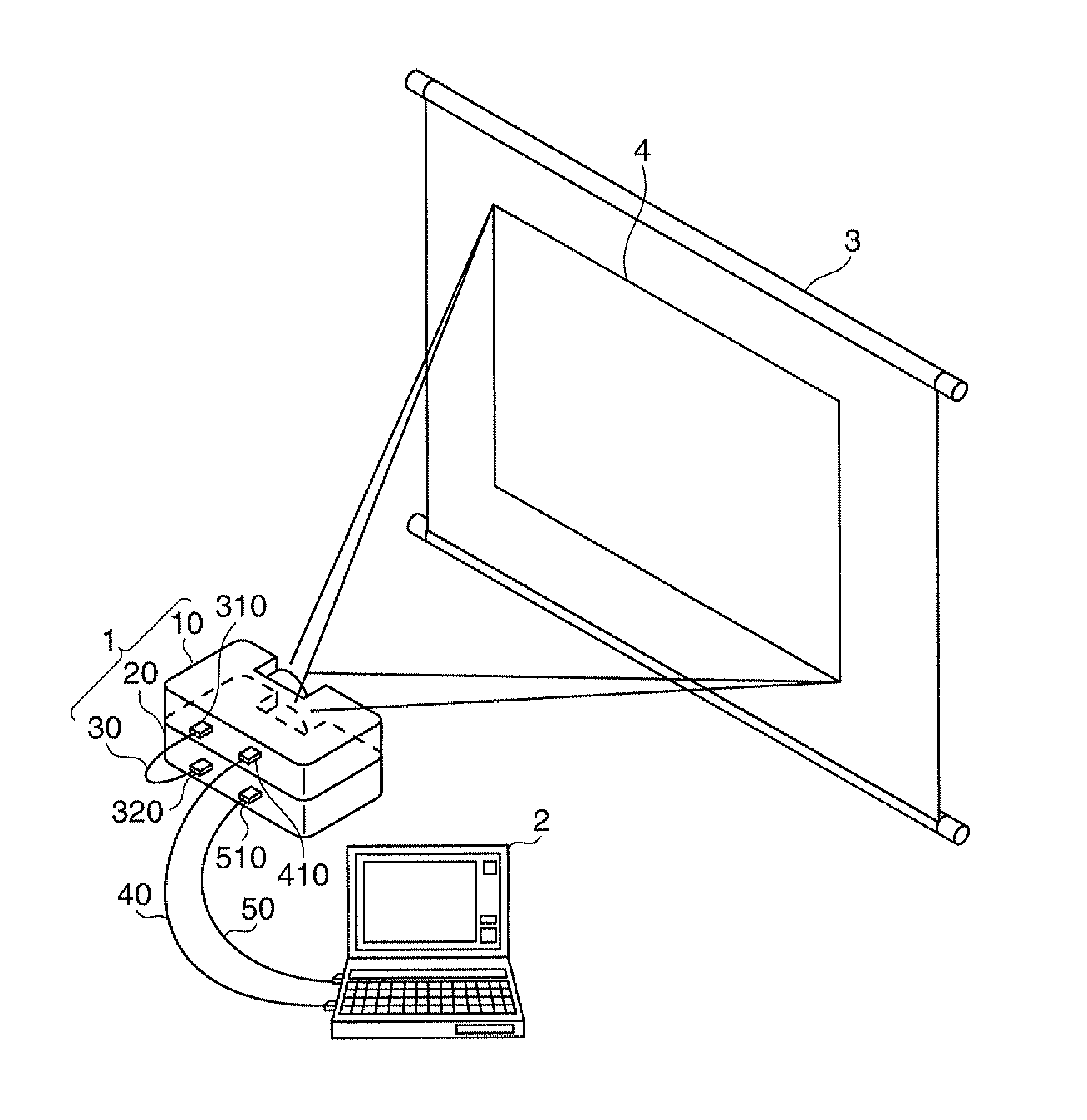
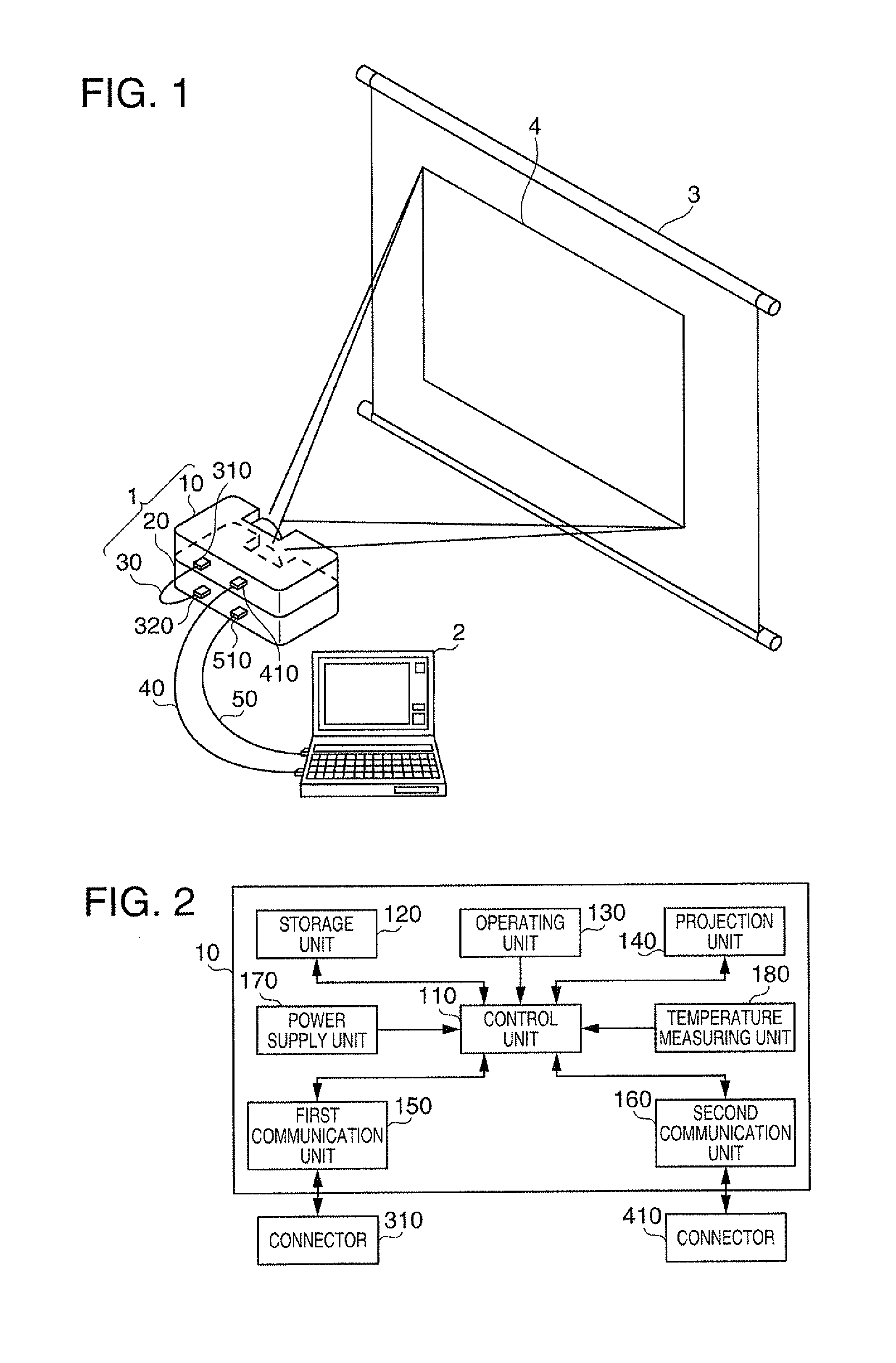
[0045]FIG. 1 is a view showing the appearance of a display system 1 according to an embodiment. The display system 1 includes a commander (master) 10, a slave 20, and a communication line 30. The commander 10 and the slave 20 are projection type display devices (so-called projectors) that project and display an image. The communication line 30 has connectors 310 and 320 at both ends. The connector 310 is connected to the commander 10, and the connector 320 is connected to the slave 20. Thus, the communication line 30 is connected to both the commander 10 and the slave 20, so that the commander 10 and the slave 20 can communicate with each other through the communication line 30. In addition, the commander 10 and the slave 20 are connected to a PC (Personal Computer; this may be a notebook type personal computer or a tablet type personal computer) 2 through cables 40 and 50, ...

modification examples

[0083]The above-described embodiment is only an example of the implementation of the invention, and may be modified as follows. In addition, the above-described embodiment and each modification example shown below may be combined and executed when necessary.

first modification example

[0084]Although the display system 1 includes two projectors in the embodiment described above, the display system 1 may include three or more projectors. Also in this case, there is one projector that transmits a command used in the stack display, that is, there is one commander, and the other projectors are slaves. In this case, there are three methods of connecting projectors to each other through the communication line 30.

[0085]FIGS. 13A to 13C are views showing methods of connecting projectors to each other in a display system including three projectors. FIG. 13A shows a case where the commander 10 and the two slaves 20 are connected in series. In this case, a projector in which the first type of error has occurred transmits the error data to the other two projectors directly or through the middle slave 20. Then, the two projectors that have received the error data display the OSD images shown in FIG. 9 or 11. Display positions of the OSD images are determined according to which...


PUM


Abstract

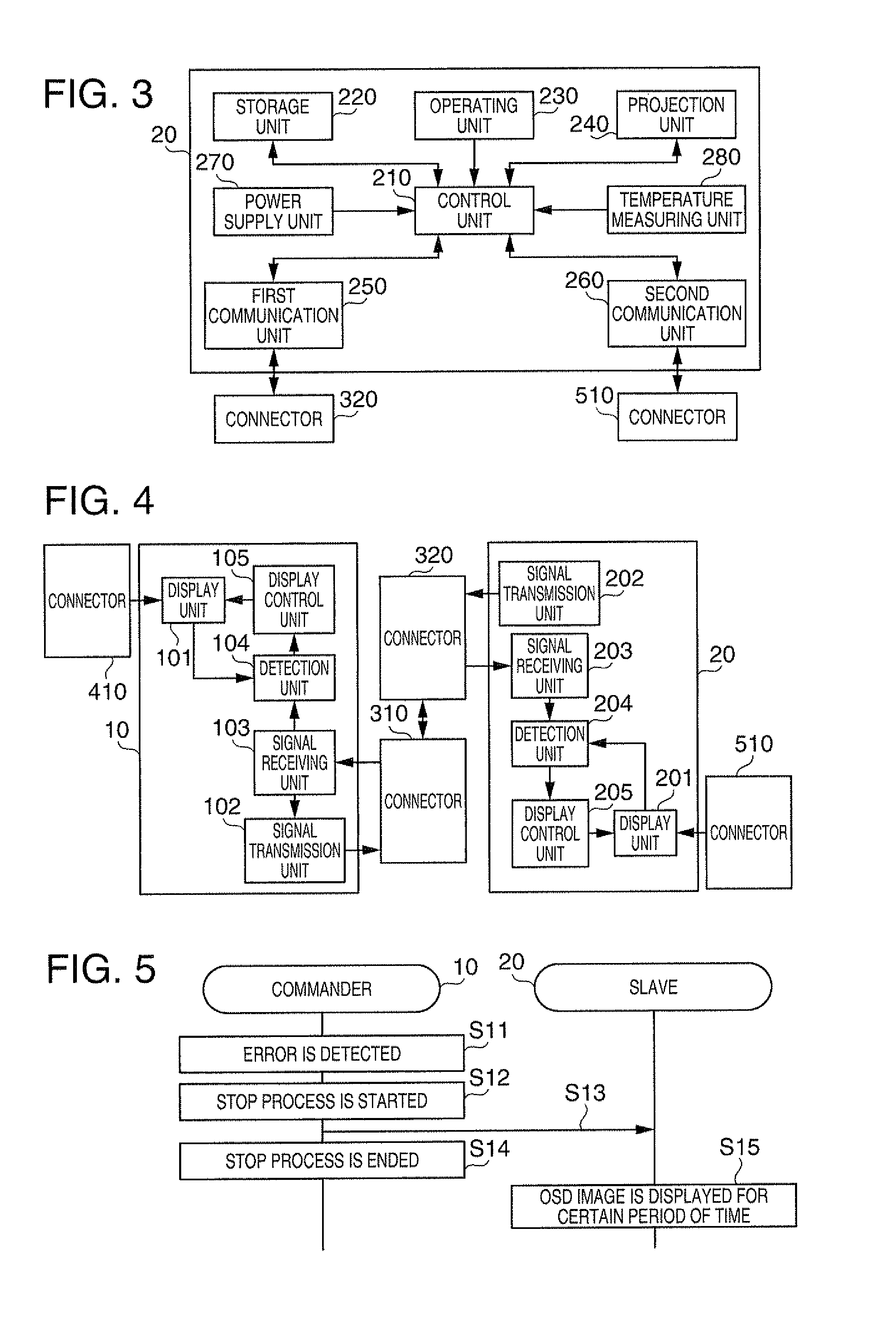
A system displays an image using a plurality of projection type display devices, and is capable of reliably notifying a user who uses the system that an error has occurred in a certain projection type display device. A slave includes a display unit that projects and displays an image and a signal receiving unit that receives data transmitted from a commander. The slave includes a detection unit that detects an error in the commander on the basis of the receiving conditions of the data in the signal receiving unit. The slave includes a display control unit that, when an error is detected by the detection unit, makes the display unit display an image showing that the error has been detected.

Description

BACKGROUND[0001]1. Technical Field[0002]The present invention relates to a technique for notifying a user that an error has occurred in a system that displays an image using a plurality of projection type display devices.[0003]2. Related Art[0004]There is a technique for notifying a user that an error has occurred in a projection type display device (so-called projector) that projects an image and displays the image on a screen or the like. JP-A-2004-13632 discloses a technique for sending an e-mail for the notification of a malfunction place to a system administrator or the like when an error is observed in the projector.[0005]Meanwhile, there is a method called “stack” in which one image is displayed more brightly than when one projection type display device is used by overlapping images displayed by a plurality of projection type display devices. When displaying an image using this method, even if an error occurs in a certain projection type display device and accordingly a corre...

Claims


Application Information

Patent Timeline
Patent Type & Authority Applications(United States)
IPC IPC(8): G09G5/00
CPCG09G2340/12G09G2330/12H04N2201/0032G09G5/003H04N9/3147H04N21/4122G06F3/1454G06F3/1423G09G5/006G09G2320/103G09G2370/04
Inventor ARUGA, TADANORIYASUDA, YUTAKAKATAHIRA, TORU
Owner SEIKO EPSON CORP
Learn More