
Selective low-temperature ohmic contact formation method for group iii-nitride heterojunction structured device

a technology of ohmic contact and heterojunction, which is applied in the direction of semiconductor devices, basic electric elements, electrical apparatus, etc., can solve the problems of deteriorating device characteristics, undesirable etching characteristics, and reduced reproducibility, so as to minimize or reduce the thermal stress applied to the substrate, minimize the damage to the gate insulating layer, and reduce the effect of thermal damage to the non-ohmic contact region

Active Publication Date: 2013-09-26
SAMSUNG ELECTRONICS CO LTD
View PDF4 Cites 9 Cited by
  • Summary
  • Abstract
  • Description
  • Claims
  • Application Information

AI Technical Summary

Benefits of technology

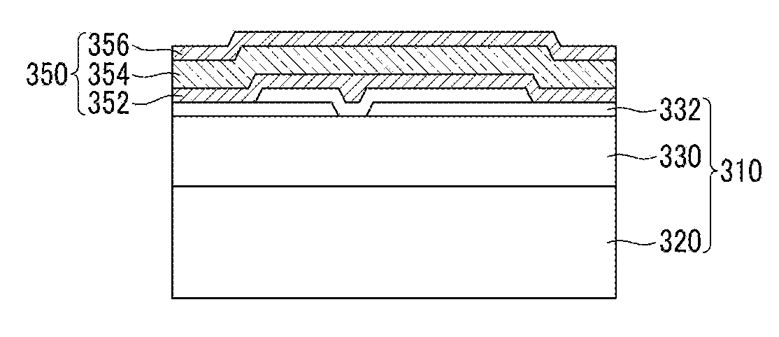
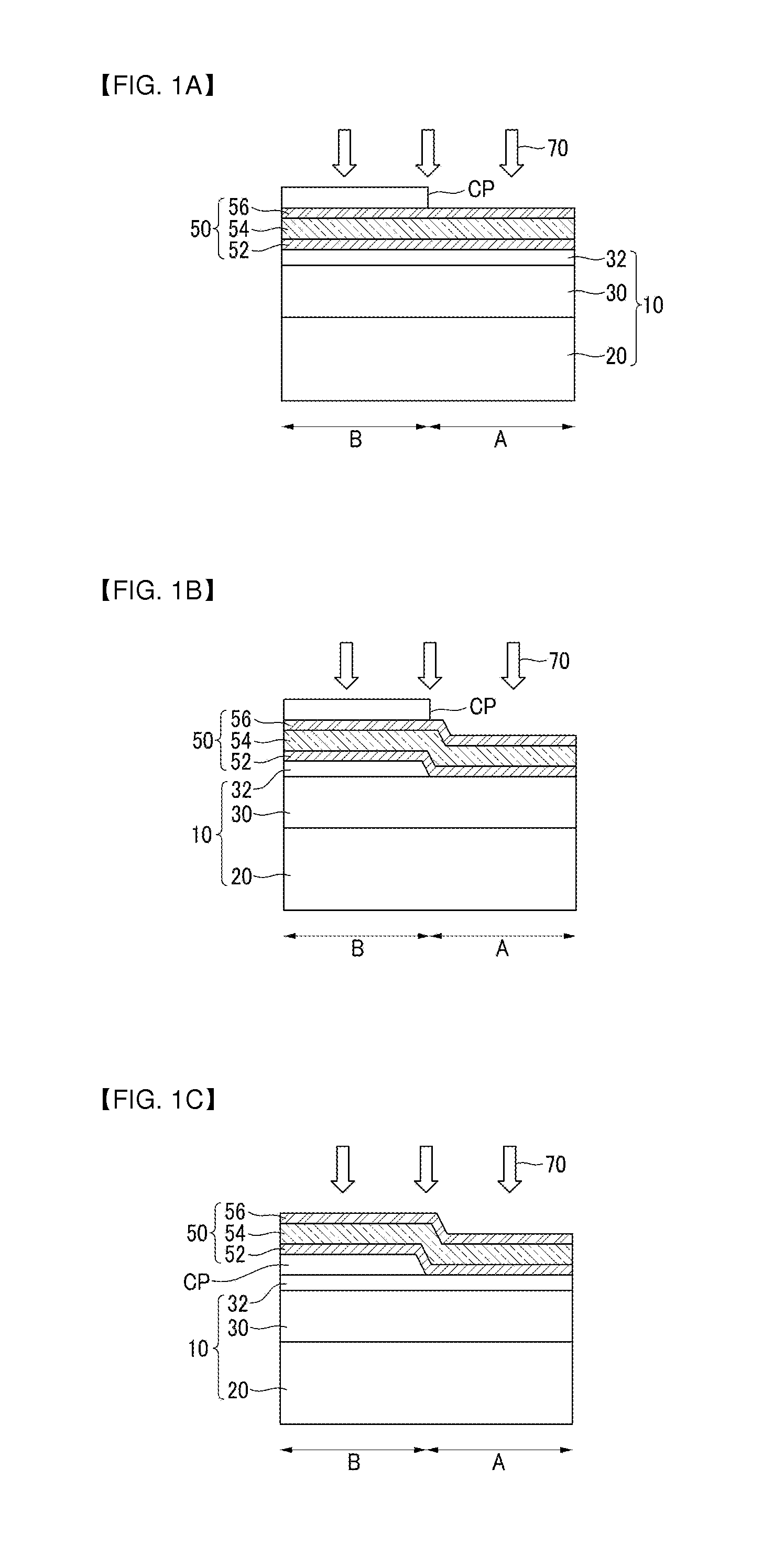
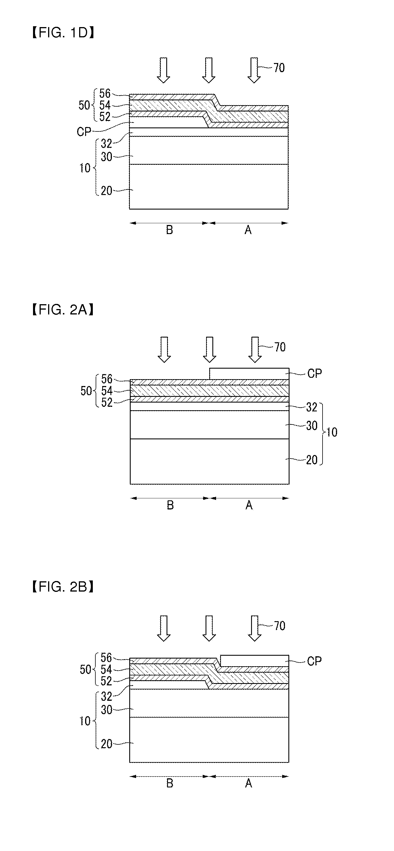
Example embodiments provide a method for making a low-temperature ohmic contact for a Group III-nitride heterojunction structured device that prevents damage to the gate insulating layer. This method is selective and economically feasible, using an etching process that can improve reproducibility. The reduced thermal stress and damage to the non-ohmic contact region may lead to improved device performance and reliability.

Problems solved by technology

However, because an ohmic contact metal layer is formed at a relatively high temperature of about 800-900° C. according to thus-far developed manufacturing methods of the Group III-nitride heterojunction structured device, the gate insulating layer exposed to a relatively high temperature process may be crystallized and / or dehydrogenated, thereby deteriorating device characteristics.
Furthermore, according to the currently used manufacturing method of the Group III-nitride heterojunction structured device, a gate electrode is formed using gold (Au) and requires a lift-off process, which is expensive and has undesirable etching characteristics, and thus has lower reproducibility.
Accordingly, economic feasibility and reproducibility of the process are relatively low.

Method used


Image

  • Selective low-temperature ohmic contact formation method for group iii-nitride heterojunction structured device
  • Selective low-temperature ohmic contact formation method for group iii-nitride heterojunction structured device
  • Selective low-temperature ohmic contact formation method for group iii-nitride heterojunction structured device

Examples


Embodiment Construction

[0027]The advantages and characteristics of the inventive concepts, and the method of achieving them, will be clearly understood referring to accompanying drawings and example embodiments.

[0028]However, the inventive concepts are not limited to the following example embodiments, and it may be realized with different embodiments. Example embodiments are provided to complete the disclosure of the inventive concepts and aid understanding of a person having ordinary knowledge in the art to fully understand the inventive concepts, and the inventive concepts are defined by the claims.

[0029]Thus, in some example embodiments, well-known technologies are not specifically described to avoid ambiguous understanding of the inventive concepts. Example embodiments may be described referring to example cross-sectional and / or schematic diagrams. Thus, the example cross-sectional and / or schematic diagrams may be modified in compliance with a manufacture technology and / or permissible errors.

[0030]Exa...


PUM


Abstract

A method for forming a selective ohmic contact for a Group III-nitride heterojunction structured device may include forming a conductive layer and a capping layer on an epitaxial substrate including at least one Group III-nitride heterojunction layer and having a defined ohmic contact region, the capping layer being formed on the conductive layer or between the conductive layer and the Group III-nitride heterojunction layer in one of the ohmic contact region and non-ohmic contact region, and applying at least one of a laser annealing process and an induction annealing process on the substrate at a temperature of less than or equal to about 750° C. to complete the selective ohmic contact in the ohmic contact region.

Description

CROSS-REFERENCE TO RELATED APPLICATION[0001]This application claims priority to and the benefit of Korean Patent Application No. 10-2002-0030245 filed in the Korean Intellectual Property Office on Mar. 23, 2012, the entire contents of which are incorporated herein by reference.BACKGROUND[0002]1. Field[0003]Example embodiments relate to a method of manufacturing a Group III-nitride heterojunction structured device, for example, a selective low-temperature ohmic contact formation method for a Group III-nitride heterojunction structure.[0004]2. Description of the Related Art[0005]A Group III-nitride heterojunction structured device stands out in the field of electric power or optics. The Group III-nitride heterojunction structured device is useful for embodying a power device or LED (light emitting device) that may discharge a high current and support a relatively high pressure.[0006]Therefore, with the recent acceleration of research and development and commercialization of photovolta...

Claims


Application Information

Patent Timeline
Patent Type & Authority Applications(United States)
IPC IPC(8): H01L21/28H01L21/18H01L21/283
CPCH01L21/268H01L21/28575H01L21/3245H01L29/2003H01L29/517H01L29/66462H01L29/452H01L21/18H01L29/737
Inventor WENXU, XIANYULEE, JEONG-YUBMOON, CHANG -YOULPARK, YONG-YOUNGYANG, WOO YOUNGOH, JAE-JOONHWANG, IN-JUN
Owner SAMSUNG ELECTRONICS CO LTD
Learn More