
Portable electric lamp with a compact casing housing a lighting module controlled by a rotary actuator

a technology of rotary actuator and electric lamp, which is applied in the direction of portable electric lighting, electric lighting without self-contained power, lighting and heating apparatus, etc., can solve the problems of increased volume of the casing, less compactness of the lamp, and inability to guarantee the tightness of such a lamp, etc., to achieve efficient and simple use

Active Publication Date: 2013-09-19
ZEDEL CORP
View PDF3 Cites 4 Cited by
  • Summary
  • Abstract
  • Description
  • Claims
  • Application Information

AI Technical Summary

Benefits of technology

The invention provides a portable electric lamp with a mechanism to prevent the lighting control actuator from spinning in certain directions. This makes it easier and safer to use. The lamp can also have a single control knob that can turn and block the actuator, allowing for separate controls for lighting power and brightness. This makes it easier for users to quickly and easily adjust the lighting in emergency situations or low visibility conditions. The actuator is fixed in translation, which makes the lamp more compact. The casing can also have stops and inserts to further prevent rotation of the actuator and improve the transmission of control between the actuator and the switch. The use of contact-free switches can also reduce the size of the casing.

Problems solved by technology

But the tightness of such a lamp is not guaranteed due to the movement of the actuator in translation.
Furthermore, a special space for movement of the actuator has to be provided in the casing, which increases the volume of the casing and makes the lamp less compact.
But such a latch blocks the actuator completely and does not enable rotation in a single direction of rotation to enable for example emergency lighting or extinguishing of the lamp.
This use is rendered difficult when the user has a limited visibility.

Method used


Image

  • Portable electric lamp with a compact casing housing a lighting module controlled by a rotary actuator
  • Portable electric lamp with a compact casing housing a lighting module controlled by a rotary actuator
  • Portable electric lamp with a compact casing housing a lighting module controlled by a rotary actuator

Examples


Embodiment Construction

[0027]A portable electric lamp 1 comprising a compact casing 2 housing a lighting module 3 preferably provided with a light-emitting diode (LED) has been represented in schematic manner in FIG. 1. Lighting module 3 can also comprise several LEDs, which can be power or standard LEDs. Portable electric lamp 1 can be a headlamp or a torch lamp, and casing 2 can be made from insulating or metallic material.

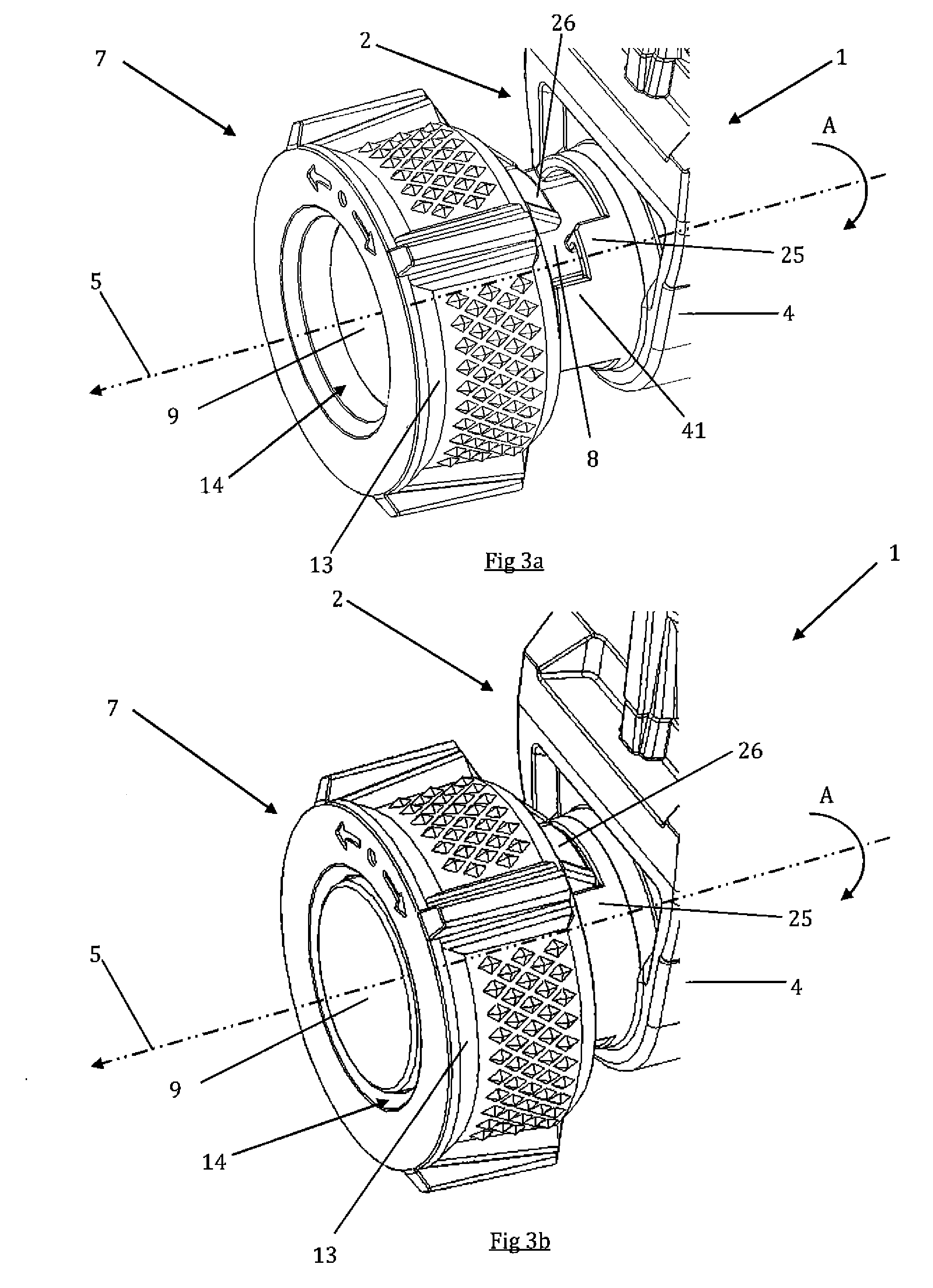
[0028]Casing 2 comprises a substantially cylindrical bottom part 4 extending along a longitudinal axis 5, and a substantially rectangular top part 6. Bottom part 4 comprises a main actuator 7 which rotates around longitudinal axis 5, also noted axis of rotation 5 of main actuator 7. Main actuator 7 enables lighting of the LED to be controlled, and is situated at a first end of bottom part 4. Main actuator 7 comprises a drive bar 8 extended at a first end by a substantially cylindrical head 9. Drive bar 8 is mounted rotating around longitudinal axis 5, and is blocked in translation wit...


PUM


Abstract

A portable electric lamp with a compact casing housing a lighting module and an electric circuit coupled to the lighting module and provided with a controlled switch, comprising an actuator rotating around an axis of rotation and mounted fixed in translation in the direction of said axis of rotation to control the switch, and a control knob rotating around the axis of rotation of the actuator, the control knob further being mounted movable in translation along the axis of rotation of the actuator between a driving position in which the control knob drives the actuator in rotation and at least one blocking position in which the control knob prevents rotation of the actuator in at least one direction of rotation.

Description

BACKGROUND OF THE INVENTION[0001]The invention relates to a portable electric lamp with a compact casing housing a lighting module controlled by a rotary actuator, and in particular a portable electric headlamp used in mountaineering.STATE OF THE ART[0002]At present, portable electric lamps of small dimensions are used comprising a lighting module housed in a casing having a compact body. The lamp generally comprises a support provided with a strap enabling the lamp to be worn on the head. The lamp further comprises an electric circuit coupled to the lighting module and provided with at least one controlled switch in order to control lighting of the lamp. The lighting module can comprise one or more light-emitting diodes (LED) or different bulbs, to provide various lighting modes, for example lighting of coloured type, white lighting, more or less intense lighting, etc. The switches can be commanded by means of a rotary actuator which moves in translation inside the casing to take a...

Claims


Application Information

Patent Timeline
Patent Type & Authority Applications(United States)
IPC IPC(8): F21V23/04
CPCF21L4/00F21L14/00F21Y2101/02F21L4/027F21V23/0414F21Y2115/10
Inventor FLORES, NICOLASBORTOLOTTI, RAPHAEL
Owner ZEDEL CORP
Learn More