
Inner focus lens, interchangeable lens device and camera system

a technology which is applied in the field of lens and lens body interchangeability, can solve the problems of inability to meet the demand for the lens having a bright f number, the inability to increase the focus speed, and the difficulty of enlarge the diameter of the lens system, etc., and achieve the effect of light weight of the focus group

Active Publication Date: 2013-09-19
PANASONIC CORP
View PDF4 Cites 3 Cited by
  • Summary
  • Abstract
  • Description
  • Claims
  • Application Information

AI Technical Summary

Benefits of technology

The present invention provides a lens that can effectively correct aberrations even at a large diameter, and increase focus speed and image shake correction. The lens has a small movement amount for focusing, is lightweight, and can correct image shake. Overall, the technical effects of the invention provide improved image quality and performance for interchangeable lens devices and cameras.

Problems solved by technology

However, in the lens system described in Japanese Patent Application Laid-Open No. 2000-347099, since a number of lenses of the groups from an image surface side with respect to a diaphraym is four, which is small, it is difficult to enlarge a diameter of the lens system, so that the demand for the lens having a bright F number cannot be met.
In each of the lens systems described in Japanese Patent Application Laid-Open No. 2011-112957 and Japanese Patent Application Laid-Open No. 2003-043348, since the lens group performing the focusing is made up of two or more lenses, the demand for the increased focus speed cannot be met.

Method used


Image

  • Inner focus lens, interchangeable lens device and camera system
  • Inner focus lens, interchangeable lens device and camera system
  • Inner focus lens, interchangeable lens device and camera system

Examples


sixth embodiments

First to Sixth Embodiments

[0046]Specific forms of inner focus lenses of the present embodiments will be described with reference to the drawings.

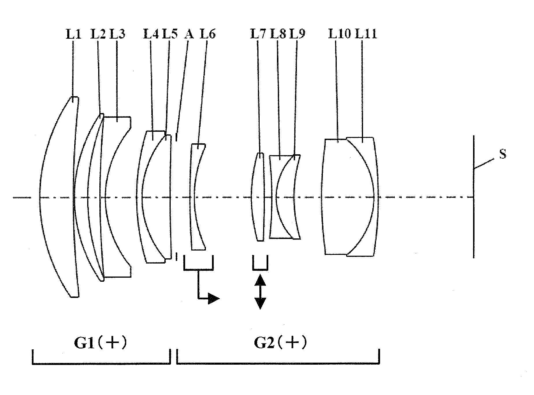
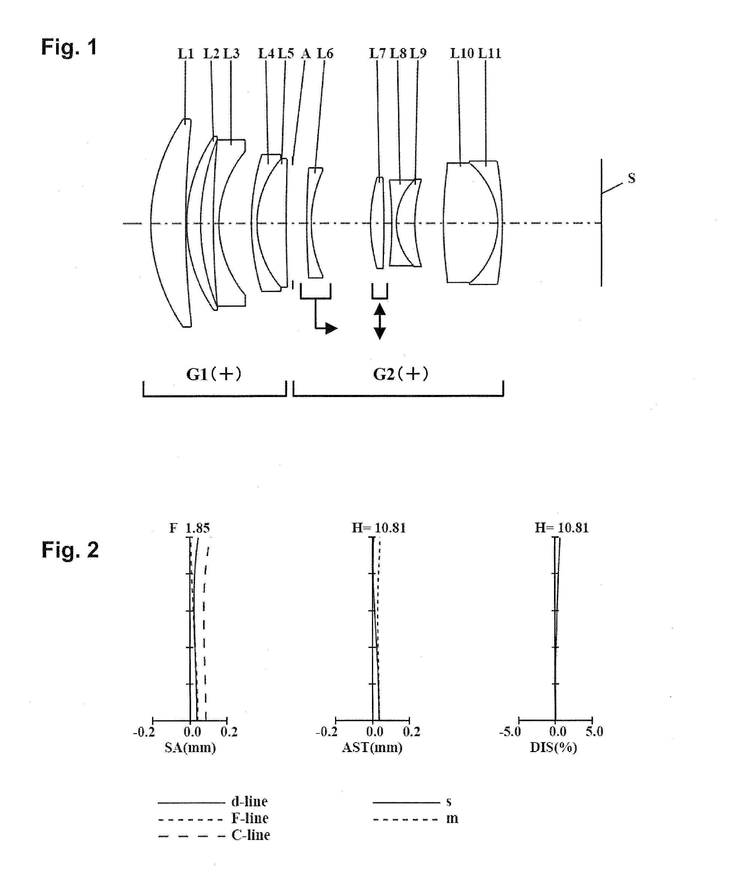
[0047]FIGS. 1, 4, 7, 10, 13, and 16 show lens configurations at the time of focusing on an object point at infinity of the inner focus lenses according to the respective embodiments. An arrow given to each lens group denotes focusing from an infinity focusing state to a close range focusing state. That is, it shows a movement direction in the focusing from the infinity focusing state to the close range focusing state. In the figures, an asterisk * given to a specific surface indicates that the surface is aspherical. Moreover, in the figures, a sign (+) or a sign (−) given to a reference numeral of each of the lens groups corresponds to a sign of power of each of the lens groups. In the respective figures, a straight line described at a rightmost position denotes a position of an image surface S.

[0048]In an inner focus lens according to Firs...

seventh embodiment

[0106]FIG. 19 is a schematic configuration diagram of an interchangeable-lens type digital camera system according to Seventh Embodiment.

[0107]The interchangeable-lens type digital camera system 100 according to the Seventh Embodiment includes a camera body 101, an interchangeable lens device 201 detachably connected to the camera body 101.

[0108]The camera body 101 includes an image pickup device 102 that receives an optical image formed by an inner focus lens 202 in the interchangeable lens device 201 to convert the optical image to an electric image signal, a liquid crystal monitor 103 that displays the image signal converted by the image pickup device 102, and a camera mounting portion 104. On the other hand, the interchangeable lens device 201 includes the inner focus lens 202 according to any one of the First to Sixth Embodiments, a lens barrel 203 holding the inner focus lens 202, and a lens mounting portion 204 connected to the camera mounting portion 104 of the camera body. ...

example 1

NUMERICAL VALUE EXAMPLE 1

[0123]

TABLE 1Surface dataSurface No.rdndvdObject surface∞132.549106.114002.0010029.12161.277300.20000327.138302.441501.8348142.7438.825802.254005153.198601.000001.7618226.6619.778505.71560740.541601.000001.8466623.8817.116305.242201.7291654.79312.370601.1952010 (Diaphragm)∞2.5004811145.129200.800001.5934967.01222.1113010.538821329.274202.368201.8042046.514−183.906501.4128015−68.724800.800001.7847225.71610.972903.205201.7291654.71726.661605.059901873.061609.688502.0006925.519−13.636100.800001.8830040.820−65.35500BFImage surface∞Various types of dataFocal distance63.9925F-number1.84985Angle of view9.5274Image height10.8150Whole lens length80.0052BF17.66880


PUM


Abstract

There are provided an inner focus lens consisting of a first lens group, an aperture diaphragm, and a second lens group in order from an object side. The first lens group has a positive first lens element, a positive second lens element, and a negative third lens element; or a positive first lens element, a positive second lens element, a positive third lens element, and a negative fourth lens element, in order from the object side. One lens element in the second lens group is moved with respect to an image surface in focusing, some of the lens elements thereof are moved in a direction perpendicular to an optical axis. The inner focus lens satisfies 0.2<|fF / fO|<3.0 (fF: a focal distance of a focus lens, fO: a synthetic focal distance of the lens elements moving in the direction perpendicular to the optical axis).

Description

BACKGROUND[0001]1. Technical Field[0002]The technical field relates to a novel inner focus lens, interchangeable lens device, and camera system. Particularly, the technical field relates to an inner focus lens suitable for an interchangeable lens attachable to a digital single-lens reflex camera or a single-lens reflex camera for silver halide film, a digital still camera and a camcorder, and an interchangeable lens device and a camera system using the inner focus lens.[0003]2. Related Art[0004]With recent increase in number of pixels of a solid-state image pickup device, higher performance has been demanded to a photographing optical system for use in this, and in addition, a lens having a bright F-number has been demanded. Furthermore, increased focus speed and a lens having small image shaking at the time of focusing have been highly demanded. Still further, demand for image shaking correction during video recording has been high, and thus, a lens system to optically correct the ...

Claims


Application Information

Patent Timeline
Patent Type & Authority Applications(United States)
IPC IPC(8): G02B27/64H04N5/232H04N23/40
CPCG02B15/14G02B27/646G02B15/177G02B15/1421G02B15/1425
Inventor KUZUHARA, SATOSHIIMAOKA, TAKUYA
Owner PANASONIC CORP
Learn More