
Sealed contact device

a contact device and sealing technology, applied in the direction of relays, circuit-breaking switch details, manufacturing tools, etc., can solve the problems of inability to promptly and surely extinguish arcs, and achieve the effect of increasing the surface area of the arc shielding member, and reducing the risk of arc fir

Active Publication Date: 2013-09-19
ORMON CORP
View PDF6 Cites 37 Cited by
  • Summary
  • Abstract
  • Description
  • Claims
  • Application Information

AI Technical Summary

Benefits of technology

This patent describes an invention for a device used to protect against electrical arLines are used to shield the device from electrical arcs. The device has a member that helps to absorb and cool the arc, which prevents damage to the device. The invention also includes a design that allows the arc to easily hit the shielding member, improving its ability to extinguish the arc. Additionally, the shielding member can be easily installed and has a cross-sectional U shape that makes it easier to grip and mount in the device. Using a metal material for the shielding member can also enhance its ability to cool the arc.

Problems solved by technology

However, the above-mentioned arc extinguisher, as illustrated in FIG. 1 of the prior art, has had a problem that an arc can be extinguished when the arc between contacts reaches an arc barrier 5, but the arc cannot be promptly and certainly extinguished when the arc does not reach the arc barrier.

Method used


Image

  • Sealed contact device
  • Sealed contact device
  • Sealed contact device

Examples


second embodiment

[0056]An arc shielding member 71 according to a second embodiment of the present invention is illustrated in FIGS. 5A and 5B.

[0057]Although the arms 63 of the arc shielding member 61 according to the first embodiment are provided with the protrusions 67, the configuration is not limited thereto. Arms 72 of a simple plate shape may be adopted like the arc shielding member 71 according to the second embodiment. With this configuration, it is possible to certainly prevent the arc from passing by the arms 72. Because other portion are the same as those of the first embodiment, like portions are denoted by like reference signs and detailed description thereof is not given.

third embodiment

[0058]An arc shielding member 73 according to a third embodiment of the present invention is illustrated in FIGS. 6A and 6B.

[0059]Although the arms 63 of the arc shielding member 61 according to the first embodiment are provided with the protrusions 67, the configuration is not limited thereto. For example, like arms 74 of the arc shielding member 73 according to the third embodiment, protruding pieces (arc receiving pieces) 77 protruding inward from an upper edge and a lower edge of an opening 76 which are provided side by side in a folded plate 75 may be formed by cutting out. Thereby, the arc shielding member 73 with a high yield of material is obtained.

[0060]Because other portion are the same as those of the first embodiment, like portions are denoted by like reference signs and detailed description thereof is not given.

fourth embodiment

[0061]An arc shielding member 80 according to a fourth embodiment of the present invention is illustrated in FIGS. 7A and 7B.

[0062]Although the arms 63 of the arc shielding member 61 according to the first embodiment are provided with the side edge ribs 66, the configuration is not limited thereto. For example, like arms 81 of the arc shielding member 80 according to the fourth embodiment, there may be provided a plurality of flexing portions (arc receiving portions) 83 each of which is bent inward from both opposed side edges of a folded plate 82, and each of which extends along the inside surface of the folded plate 82. This configuration allows an increase in surface area of the arms 81 so that the arms can be easily hit by the arc, and certainly prevents the arc from passing to the back side. Because other portion are the same as those of the first embodiment, like portions are denoted by like reference signs and detailed description thereof is not given.


PUM

PropertyMeasurementUnit
Magnetic forceaaaaaaaaaa

Abstract

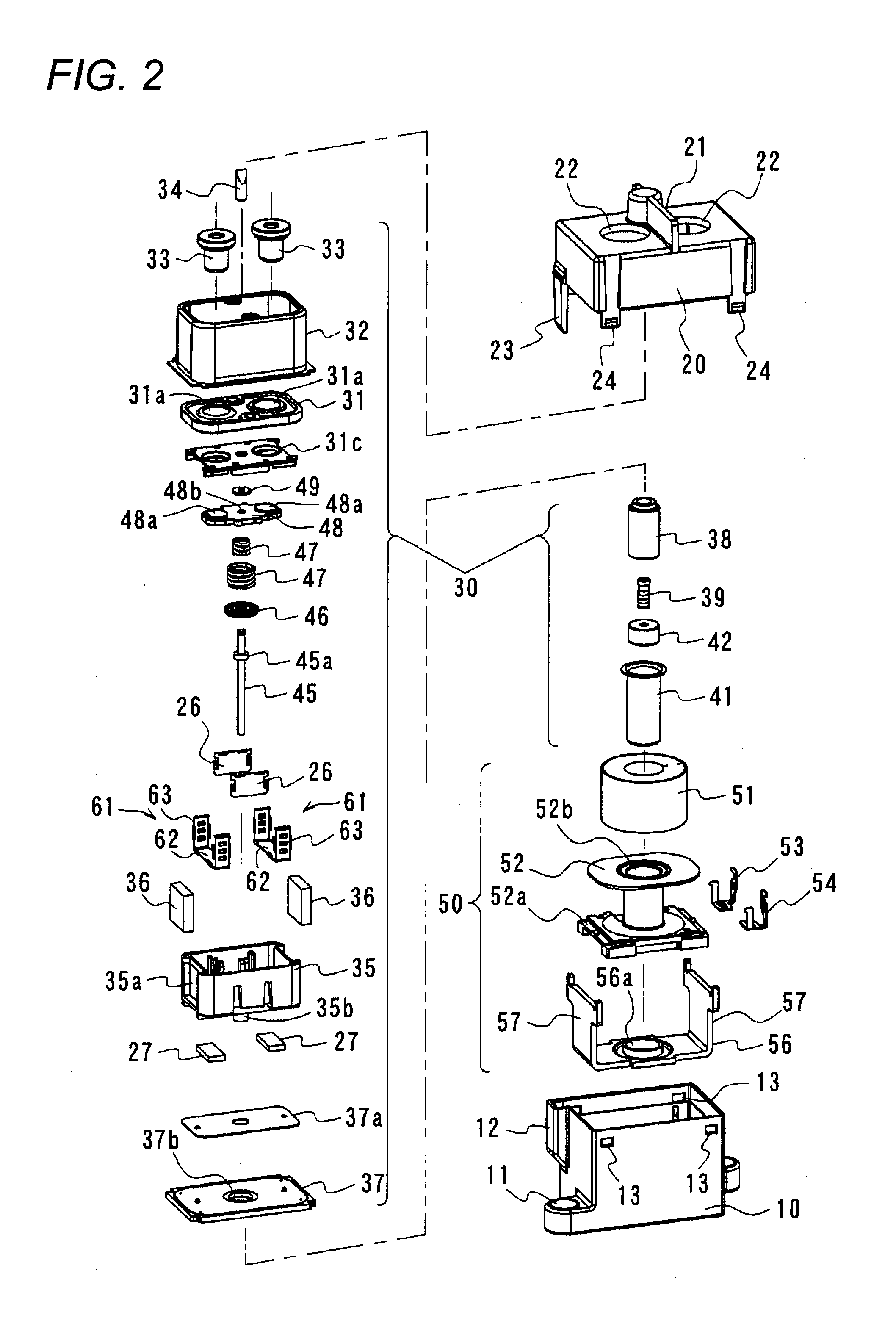
The invention provides a sealed contact device capable of extinguishing an arc which extends in an arbitrary direction. The sealed contact device includes a housing; a fixed contact and a movable contact disposed in the housing in such a manner as to face each other; and permanent magnets which are disposed with the fixed contact and the movable contact interposed therebetween and which attracts an arc between the fixed contact and the movable contact using a magnetic force. An arc shielding member is disposed at a position to which the arc is attracted by current flowing between the fixed contact and the movable contact and by the magnetic force between the permanent magnets, in the housing.

Description

BACKGROUND OF THE INVENTION[0001]1. TECHNICAL FIELD[0002]The present invention relates to a sealed contact device, and more particularly to an electromagnetic relay for power loads which can promptly extinguish an arc which occurs.[0003]2. RELATED ART[0004]In the related art, as an arc extinguisher used in a sealed contact device, for example, Japanese Unexamined Patent Publication No. 2005-285547 discloses a device which extinguishes an arc occurring between a movable contact piece and a fixed contact piece when a contact of the fixed contact piece is separated from a contact of the movable contact piece by narrowing the arc between right and left sidewalls of an arc barrier.[0005]However, the above-mentioned arc extinguisher, as illustrated in FIG. 1 of the prior art, has had a problem that an arc can be extinguished when the arc between contacts reaches an arc barrier 5, but the arc cannot be promptly and certainly extinguished when the arc does not reach the arc barrier.[0006]Th...

Claims


Application Information

Patent Timeline
IPC IPC(8): B23K9/32
CPCH01H9/36H01H9/443B23K9/32H01H51/29H01H50/20H01H9/34H01H73/18
Inventor YANO, KEISUKEHAYASHIDA, YASUOHASHIMOTO, RYUICHIMORI, SHINGOOKAMOTO, TAKUMA
Owner ORMON CORP
Learn More