
Indoor unit of air-conditioning apparatus

a technology for air conditioners and indoor units, applied in the field of indoor units of air conditioners, can solve problems such as loss of wireless remote controllers, and achieve the effect of increasing convenience and finding easy and quickly

Inactive Publication Date: 2013-09-05
MITSUBISHI ELECTRIC CORP
View PDF1 Cites 5 Cited by
  • Summary
  • Abstract
  • Description
  • Claims
  • Application Information

AI Technical Summary

Benefits of technology

The present invention is an air-conditioning apparatus with a wireless remote controller that can be easily found. The wireless remote controller produces sound, light, or vibration when the user approaches it and faces the image pickup device for face recognition. This allows the user to quickly and easily find the wireless remote controller without having to operate it. The technical effect of this invention is increased convenience for users.

Problems solved by technology

Meanwhile, however, since the wireless remote controller is not fixedly placed at the same position, the wireless remote controller may be lost.

Method used


Image

  • Indoor unit of air-conditioning apparatus
  • Indoor unit of air-conditioning apparatus
  • Indoor unit of air-conditioning apparatus

Examples


embodiment 1

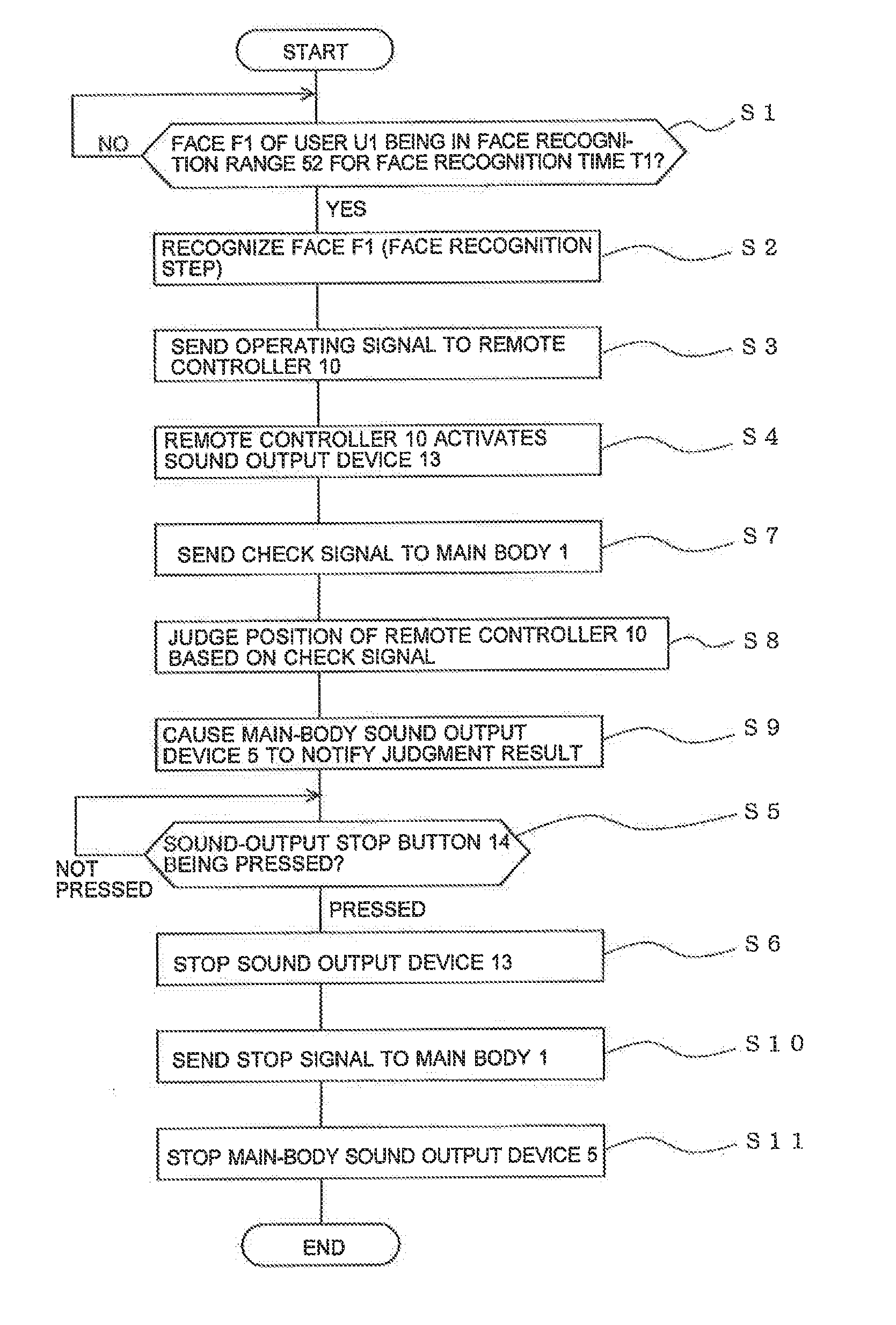
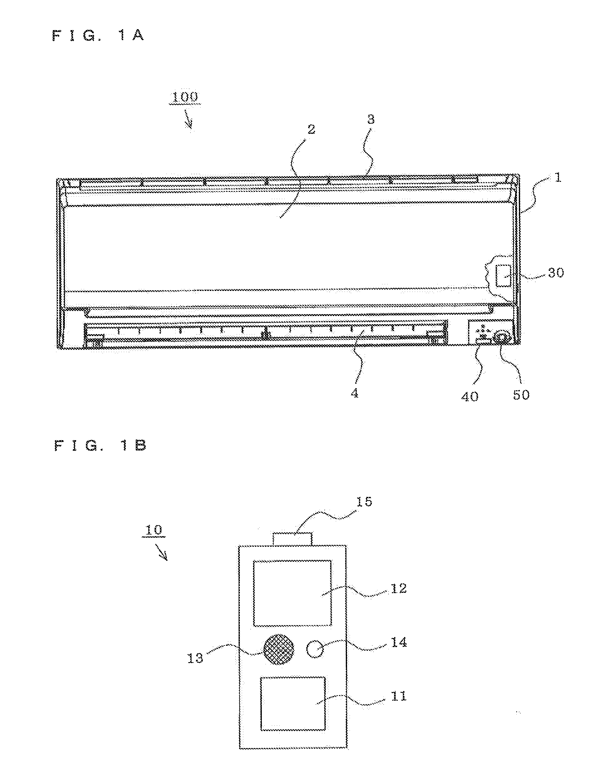
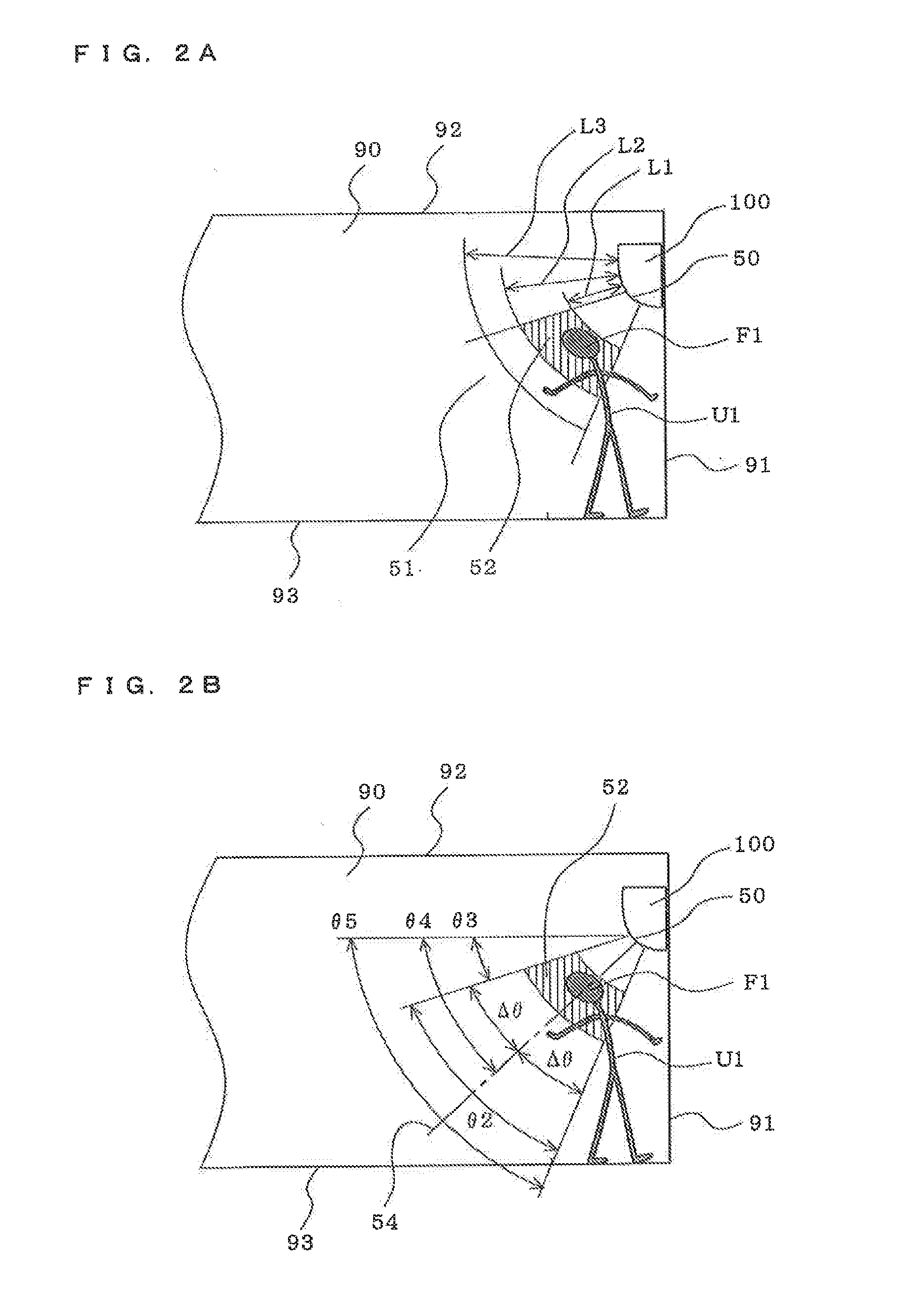
[0017]FIGS. 1 to 3 explain an indoor unit of an air-conditioning apparatus according to Embodiment 1 of the present invention. FIG. 1A is a front view of a main body. FIG. 1B is a front view of a wireless remote controller. FIGS. 2A and 2B are side views each showing a function (recognition by face recognition). FIG. 3 is a flowchart showing a flow of an operation. It is to be noted that the respective drawings are schematically illustrated, and the present invention is not limited to Embodiment 1 shown in the drawings.

[0018](Main Body)

[0019]In FIG. 1A, an indoor unit 100 of the air-conditioning apparatus (hereinafter, called “indoor unit”) includes a main body 1 having an air inlet 3 formed in an upper portion and an air outlet 4 formed in a lower portion, a front panel 2 that covers a front surface of the main body 1 in a manner that the front panel 2 can be opened and closed, a fan (not shown) that intakes the indoor air from the air inlet 3 and forms an air path to the air outle...

embodiment 2

[0044]FIGS. 4 and 5 explain an indoor unit of an air-conditioning apparatus according to Embodiment 2 of the present invention. FIG. 4 is a front view of a main body. FIG. 5 is a flowchart showing a flow of an operation. Parts the same as or corresponding to those in Embodiment 1 refer the same reference signs, and the description is partly omitted.

[0045]In FIG. 4, a main-body sound output device 5 that outputs voice is provided at a main body 1 of an indoor unit 200 of the air-conditioning apparatus (hereinafter, called “indoor unit”).

[0046](Controller)

[0047]In FIG. 5, a controller 30 of the indoor unit 200 determines whether or not the face F1 of the user U1 is present within the face recognition range 52 at least for the face recognition time T1 (for example, 5 seconds) (S1).

[0048]Then, if the face F1 of the user U1 is present within the face recognition range 52 for the face recognition time T1, the face F1 is recognized (S2).

[0049]In contrast, if the face F1 is not recognized, ...


PUM


Abstract

An indoor unit of an air-conditioning apparatus is provided, the indoor unit which can easily cause a wireless remote controller to output sound and does not degrade the design of an appearance of a main body. A main body 1 includes a main-body communication device 40 that communicates with a wireless remote controller 10, an image pickup device 50 that captures an image of the inside of a room, and a controller 30. The wireless remote controller 10 includes a wireless-remote-controller communication device 15 and a sound output device 13. When the face of a person is present within a face recognition range in a field of the image pickup device 50 for a face recognition time, the controller 30 recognizes the face of the person. If the controller 30 recognizes the face of the person, the controller 30 causes an operating signal to be sent to the wireless remote controller 10. When the wireless remote controller 10 receives the operating signal, the wireless remote controller 10 activates the sound output device 13 and causes the sound output device 13 to output sound.

Description

TECHNICAL FIELD [0001]The present invention relates to indoor units of air-conditioning apparatuses, and more particularly relates to an indoor unit of an air-conditioning apparatus including a wireless remote controller (remote operation means).BACKGROUND ART [0002]Conventionally, in order to enhance usability of a user (equivalent to an operator), a wireless remote controller (remote operation means) for remotely operating an air-conditioning apparatus is provided, Since the wireless remote controller is wireless, allowing the user to operate an indoor unit of the air-conditioning apparatus from anywhere in the room. Meanwhile, however, since the wireless remote controller is not fixedly placed at the same position, the wireless remote controller may be lost.[0003]Owing to this, an invention is disclosed (for example, see Patent Literature 1), in which a wireless remote controller includes sound output means and the wireless remote controller outputs sound in response to a comma...

Claims


Application Information

Patent Timeline
Patent Type & Authority Applications(United States)
IPC IPC(8): G08C17/02
CPCG08C17/02F24F2011/0091F24F2011/0068F24F11/0086F24F11/0009F24F11/0034F24F11/30F24F2120/10F24F11/56F24F11/52F24F2120/12F24F11/526F24F2120/00G06T2207/30201
Inventor MATSUMOTO, TAKASHI
Owner MITSUBISHI ELECTRIC CORP
Learn More