
Medical screw

a screw and screw body technology, applied in the field of medical screws, can solve the problems of difficult pulverizing out of the screw, callus needs to be removed, etc., and achieve the effect of reliably, easily, and quickly pulverizing from inside the bone, and reliably, easily and quickly

Active Publication Date: 2018-12-04
TAMA MEDICAL
View PDF21 Cites 0 Cited by
  • Summary
  • Abstract
  • Description
  • Claims
  • Application Information

AI Technical Summary

Benefits of technology

The invention provides a medical screw that can be easily and quickly withdrawn from the bone using a reverse external thread portion formed on the outer periphery of the head portion after the bone has unified or at the time of replacement. This solves a problem that previously existed when trying to remove the screw from the bone.

Problems solved by technology

In this case, since the callus becomes an obstacle which makes the rotational operation jig 3 difficult to fit into the rotational operating portion if of the screw 1, the callus needs to be removed.
At the time of being pulled out, the screw 1 is moved upward by a reaction force of the bone C until the screw thread portion 1b screwed into the bone C reaches the bone cortex surface E. However, in the case where the screw 1 is still buried in the subcutaneous structure B, the screw thread portion 1b runs idle and thus puling out of the screw 1 becomes difficult.

Method used


Image

  • Medical screw
  • Medical screw
  • Medical screw

Examples


Embodiment Construction

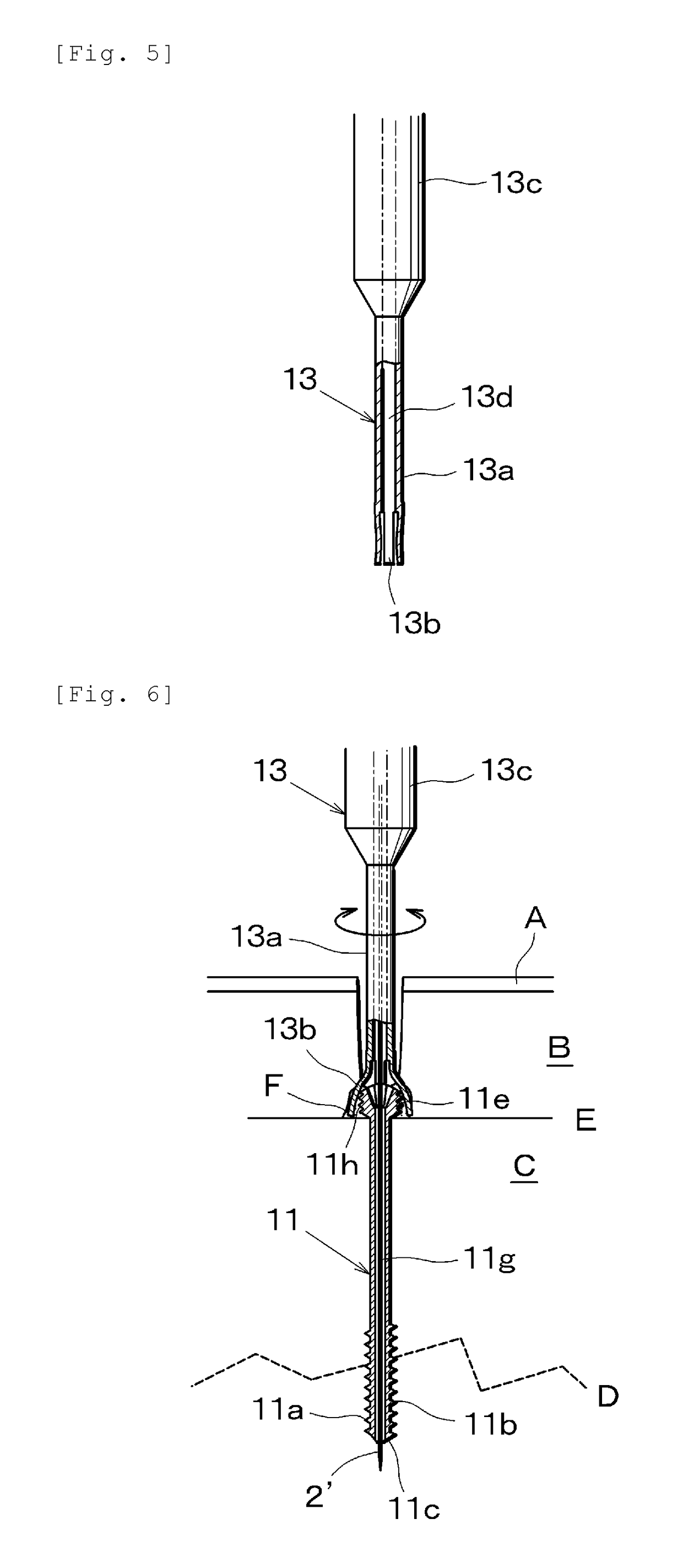
[0036]The invention will be described in detail with reference to embodiments illustrated in FIG. 1 to FIG. 11.

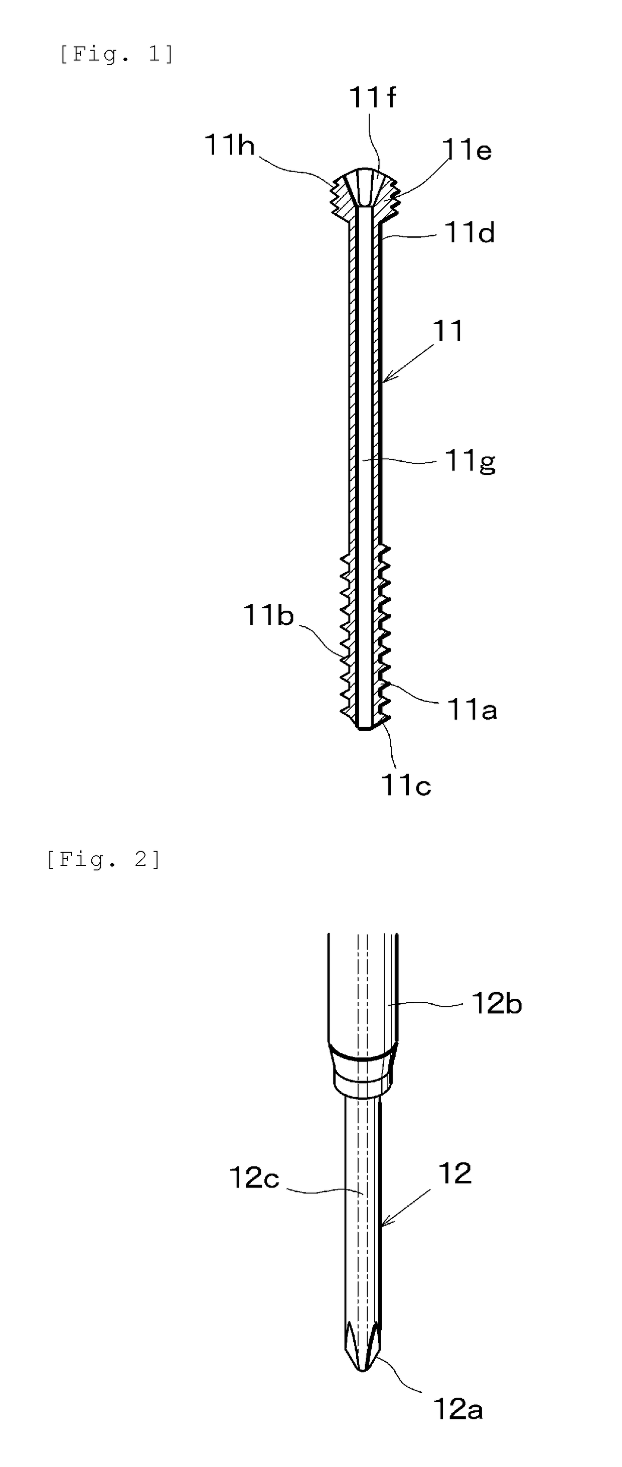
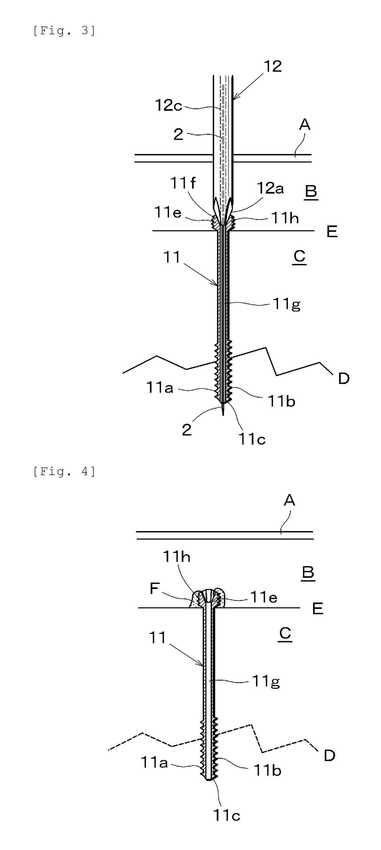
[0037]FIG. 1 is a cross-sectional view of a medical screw 11 of an embodiment. A distal end portion 11a of the tube-shaped screw 11 formed of a metallic material such as titanium is provided with a screw thread portion 11b, which is a right-handed thread, formed on an outer surface thereof and is provided with a drill blade 11c at an extremity thereof. The screw thread portion 11b may be provided not only on the distal end portion 11a, but also on the outer surface entirely in a longitudinal direction of the screw 11.

[0038]A rear end portion 11d is provided with a head portion 11e at a distal end thereof, and is provided with a rotational operating portion 11f formed into, for example, a cross-shaped plus groove configured to fit in a distal end portion of a screwing-in operating jig, which will be described later, at a center portion of a top surface of the head portion 11...


PUM


Abstract

The outer periphery of a head section (11e) of a medical screw (11) is provided with an inverse external screw thread (11h) that is formed in the opposite screw direction from that of a screw thread (11b) provided to a tip section (11a). An inverse internal screw thread (14a) provided to the leading end of a rod-shaped body constituting an extraction jig (14) is rotated in the opposite direction from the screw direction of the screw thread (11b) so as to be screwed onto the inverse external screw thread (11h) and thereby integrate the screw (11) and the extraction jig (14). The screw (11) is gently extracted from the bone fracture site (D) and is removed from the body by rotating the extraction jig in the reverse direction from the insertion direction of the screw (11).

Description

TECHNICAL FIELD[0001]The present invention relates to a medical screw for joining a fracture site and a withdrawal operating jig for a medical screw.BACKGROUND ART[0002]PTL 1 discloses a medical screw 1 having a hollow hole, which is referred to as a cannulated screw as illustrated in FIG. 12. The screw 1 is used for joining a fracture site in a medical field in the related art, is provided with a screw thread portion 1b formed on an outer surface of a distal end portion 1a, is provided with a drill blade 1c formed at an extremity thereof, and is provided with a through hole 1d extending along a center axis along an entire length thereof. A rotational operating portion if formed of, for example, a hexagonal depression is provided at an entry of the through hole 1d of a head portion 1e of the screw 1, and the fracture site is joined by screwing the screw thread portion 1b into a bone by fitting a distal end portion of a driver-type rotational operation jig into the rotational operati...

Claims


Application Information

Patent Timeline
Patent Type & Authority Patents(United States)
IPC IPC(8): A61B17/86A61B17/88
CPCA61B17/8891A61B17/862A61B17/8888A61B17/8615A61B17/8883A61B17/864A61B17/7082A61B17/84
Inventor MACHIDA
Owner TAMA MEDICAL
Learn More