
Method and device for testing an electronic appliance

a technology for electronic appliances and testing methods, applied in the direction of electronic circuit testing, measurement devices, instruments, etc., can solve the problem that it is difficult to completely avoid interference from external sources, and achieve the effect of reducing the influence of external fields on the sensor signal

Active Publication Date: 2013-09-05
JOYSON SAFETY SYST GERMANY GMBH
View PDF5 Cites 1 Cited by
  • Summary
  • Abstract
  • Description
  • Claims
  • Application Information

AI Technical Summary

Benefits of technology

The device described in this patent can filter out external electromagnetic interference that can affect the signal produced by a sensor. This is done by detecting certain characteristics of the interference and using correcting means to modify the electronic signal. This results in a cleaner, more accurate sensor signal.

Problems solved by technology

However, it is hardly possible to entirely avoid interferences by external sources of interference, particularly, when the electronic appliance is movable.

Method used


Image

  • Method and device for testing an electronic appliance
  • Method and device for testing an electronic appliance
  • Method and device for testing an electronic appliance

Examples


Embodiment Construction

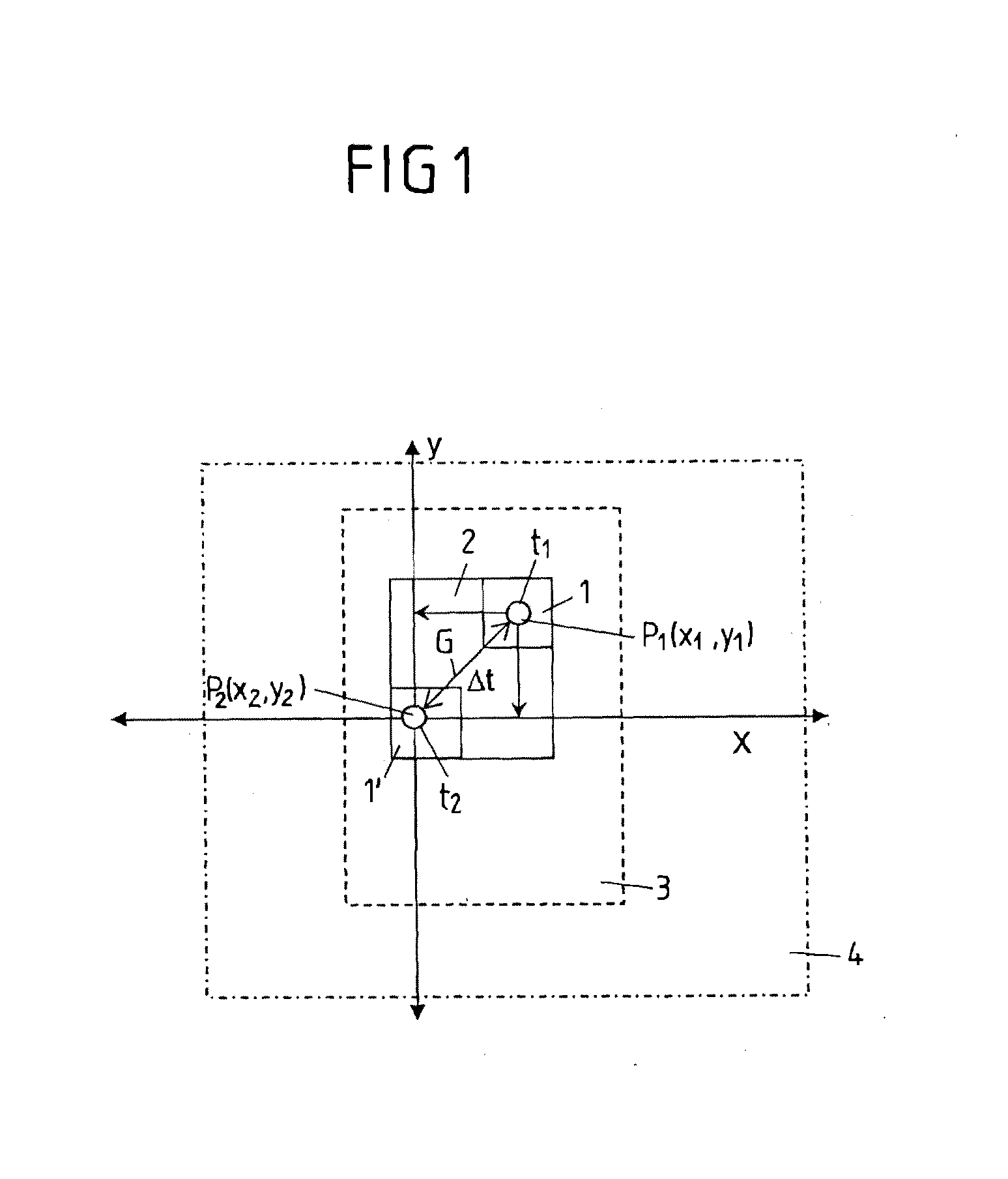
[0078]FIG. 1 shows a coordinate system in which values (x1, x2) of a first parameter X and values (y1, y2) of a second parameter Y of an electric signal, produced by an electronic appliance which is to be tested, are plotted. For example, the first parameter is a quadrature portion of an alternating current signal produced by the electronic appliance and the second parameter is a reactive current of the alternating current signal. The electronic appliance under consideration is particularly designed in the form of a sensor which is correspondingly loaded with an AC voltage.

[0079]At a first point in time t1 the system, to which the electronic appliance which is to be tested is allocated, is in an approximatively stationary state, so that variables of the system fluctuate only slightly around a stationary value. Based on the concrete application of the electronic appliance, i.e. of the system allocated to it which is designed in the form of a physical system in the example of FIG. 1, ...


PUM


Abstract

A method and a device for testing an electronic appliance for determining at least one variable of a system. The electronic appliance is designed in the form of a sensor. The method includes defining an expected minimum and / or maximum value of the variable and producing an electric signal by means of the electronic appliance depending on the variable. The method also includes detecting at least one value of a parameter of the produced electric signal and defining an expected minimum and / or maximum value of the parameter depending on the defined minimum and / or maximum value of the variable of the system. A determination is made, based on whether the detected value of the parameter is greater than the minimum value defined for the parameter and / or smaller than the maximum value, whether there is a malfunction of the electronic appliance provoked by an external electromagnetic interference field.

Description

CROSS-REFERENCE TO A RELATED APPLICATION[0001]This application is a continuation of International Patent Application Number PCT / EP2011 / 052665, filed on Feb. 23, 2011, which was published in German WO 2011 / 107381. The foregoing international application is incorporated by reference herein.BACKGROUND OF THE INVENTION[0002]The invention relates to methods for testing an electronic appliance, which serves for determining at least one variable, as well as to a device for testing an electronic appliance for determining at least one variable.[0003]Methods and devices to detect or simulate malfunctions of electronic appliances, e.g. in the form of sensors, are known from prior art. In particular, devices are known to keep interferences provoked by external electric sources of interference as low as possible, i.e. to obtain as good an electromagnetic compatibility (EMC) of the electronic appliance as possible.[0004]However, it is hardly possible to entirely avoid interferences by external so...

Claims


Application Information

Patent Timeline
Patent Type & Authority Applications(United States)
IPC IPC(8): G01R31/28
CPCG01D3/08G01R31/28G01R31/2829
Inventor KANDLER, MARCUSSALZIGER, JAN MICHAEL
Owner JOYSON SAFETY SYST GERMANY GMBH
Learn More