
Front wheel energy recovery system

a technology of energy recovery and front wheels, which is applied in the direction of vehicle position/course/altitude control, process and machine control, instruments, etc., can solve the problems of large battery size, increased cost, and insufficient battery technology, so as to avoid creating a torque steering effect, improve vehicle dynamics and safety for the rider, and easily install a hydraulic version

Inactive Publication Date: 2013-08-29
W MORRISON CONSULTING GRP
View PDF5 Cites 6 Cited by
  • Summary
  • Abstract
  • Description
  • Claims
  • Application Information

AI Technical Summary

Benefits of technology

[0019]An advantage of an embodiment of the claimed front wheel KERS system for a motorcycle may be to provide a mechanical system with counterbalanced torque reactions and moments of inertia for the portion of the KERS system that is co-located with the front wheel and suspension so as to avoid creating a torque steering effect. This in turn improves the vehicle dynamics and safety for the rider.
[0020]Another advantage of an embodiment of the claimed front wheel KERS system for a motorcycle may be the ability to easily install a hydraulic version of the claimed invention to a new or existing motorcycle with minimal modifications.
[0021]Another advantage of an embodiment of the claimed front wheel KERS system for a motorcycle may be the ability to transmit substantial energy from the front wheel to an electricity generating device located separately from the front wheel without interfering with steering range of motion or the telescoping action of the front suspension.
[0022]Another advantage of an embodiment of the claimed front wheel KERS system for a motorcycle may be the ability to transfer substantial energy from the front wheel to extend the life of the on-board electrical accumulator charge and thus allow for the use of more powerful motors with smaller battery packs that would otherwise be quickly discharged.
[0023]Another advantage of an embodiment of the claimed front wheel KERS system for a motorcycle may be the ability to transfer substantial energy from the front wheel to extend the life of the electrical accumulator charge and thus allow for a motorcycle with a fixed capacity motor and electrical accumulator to travel over an extended range relative to a non-KERS system equipped motorcycle of the same capacity motor and electrical accumulator.
[0024]Another advantage of an embodiment of the claimed front wheel KERS system for a motorcycle may be to provide a system that allows for comprehensive control over the KERS system both by manual and / or automatic controls.

Problems solved by technology

One major concern with using electric motors in vehicle design is battery life and battery size, which impact vehicle power and range, especially on motorcycles where space to accommodate batteries is extremely limited.
Battery size becomes a key issue as consumers are demanding that electric vehicles operate at extended ranges that require larger and thus heavier batteries that are more costly and are not conducive to small vehicles such as motorcycles.
Today's battery technology does not provide for long duration sufficient to make an electric two or three-wheeled vehicle competitive with its gasoline powered counterparts, and so manufacturers have been slow to produce electric motorcycles.
Kinetic energy recovery has been developed for electrically powered four-wheel production and race vehicles, but the systems developed for four-wheel vehicles (hereinafter “cars”) are not able to be effectively utilized in motorcycles due to issues relating to size, weight, vehicle stability, and for additional and non-obvious reasons.
One fundamental problem of wheel motors is they must be of a large enough capacity to harvest a meaningful amount of energy sufficient to justify their weight and cost.
To capture this energy for use in battery charging would require a 150 horsepower wheel motor to be installed inside the front wheel, which would weigh more than 100 lbs and be extremely expensive.
Additionally, the effect of adding more than 100 lbs to the front wheel of a motorcycle would create an extremely unstable and dangerous vehicle dynamics situation, since steering, balance, wheel size, and unsprung weight are all degraded considerably, assuming the bulky 150 horsepower motor could even be packaged inside a front wheel in the first place.
Yet despite the steady increase of manufacturer interest in electric cars and the ease with which they may deploy a KERS system on their front wheel drive designs, electric motorcycles are extremely rare, and almost none of those that have been built use any kind of regenerative braking systems.
This is because conventional wisdom in the field of electric motorcycles holds that since the electric motor is mechanically coupled to drive the rear wheel (where there is little regenerative benefit under braking due to the light loading of the rear wheel as previously discussed) such systems are ineffective on a motorcycle.
To the knowledge of the inventors of this application, no one in the art of electric motorcycle design has even recognized and certainly not addressed the problem of how to recover the abundant energy available from the front wheel of a motorcycle under braking, which is otherwise wasted as heat.
Another factor that has caused the electric motorcycle industry to ignore KERS systems is the very high crash danger arising from the use of rear wheel regeneration because applying any braking torque to a lightly loaded rear wheel, especially when leaning into a turn, easily locks up the wheel and causes rapid loss of traction and control.
Other KERS system constructions may be used such as via hydraulic accumulators or flywheel storage, but like wheel motors, each have drawbacks that render them inappropriate for motorcycle applications.
The use of a high pressure accumulator sufficient to provide a meaningful KERS system benefit on a motorcycle, coupled with the inefficiencies inherent in this type of accumulator system make it impractical for a motorcycle.
While this is a noteworthy improvement in fuel economy, the packaging and handling impact on a motorcycle with a 40,000 RPM flywheel mounted to it combined with the extreme cost, cooling requirements, and limited energy storage make flywheels impractical for motorcycles.
The application of gears, shafts, pumps and other such structures to the front wheel and suspension of a motorcycle presents a number of challenges as it is easy to upset the safe handling characteristics of a two or three-wheeled vehicle, which are more sensitive to such changes than are cars.
U.S. Pat. No. 6,505,699 does not disclose or provide any teaching on recovering energy from the front wheel for use in recharging batteries or for any other purpose, and actually precludes such energy transfer by the teaching of one-way freewheel sprag clutches in the front wheel that operate to allow the motor to drive the front wheel but do not allow the front wheel to back drive the motor for regeneration.
Additionally, U.S. Pat. No. 6,505,699 does not even disclose implementation in an electric powered vehicle.
It is clear that manufacturers and inventors of electric motorcycles have failed to recognize and address the problem of recovering kinetic energy from the front wheel.
Limited efforts have been made to implement rear wheel KERS systems, but the poor regeneration provided by the lightly loaded rear tire have led most to abandon the pursuit of on-board recharging altogether.
Industry experts have been quoted as saying that KERS systems on a motorcycle are a waste of time.
Unfortunately, the limited battery capacities available in the current state of the art combined with the industry's failure to recognize or employ the front wheel as a source of significant recharging energy, has combined to relegate the fledgling electric motorcycle industry to novelty status with an uncertain future due to limited vehicle range and performance.

Method used


Image

  • Front wheel energy recovery system
  • Front wheel energy recovery system
  • Front wheel energy recovery system

Examples


Embodiment Construction

[0058]Reference will now be made in detail to various embodiments, examples of which are illustrated in the accompanying drawings.

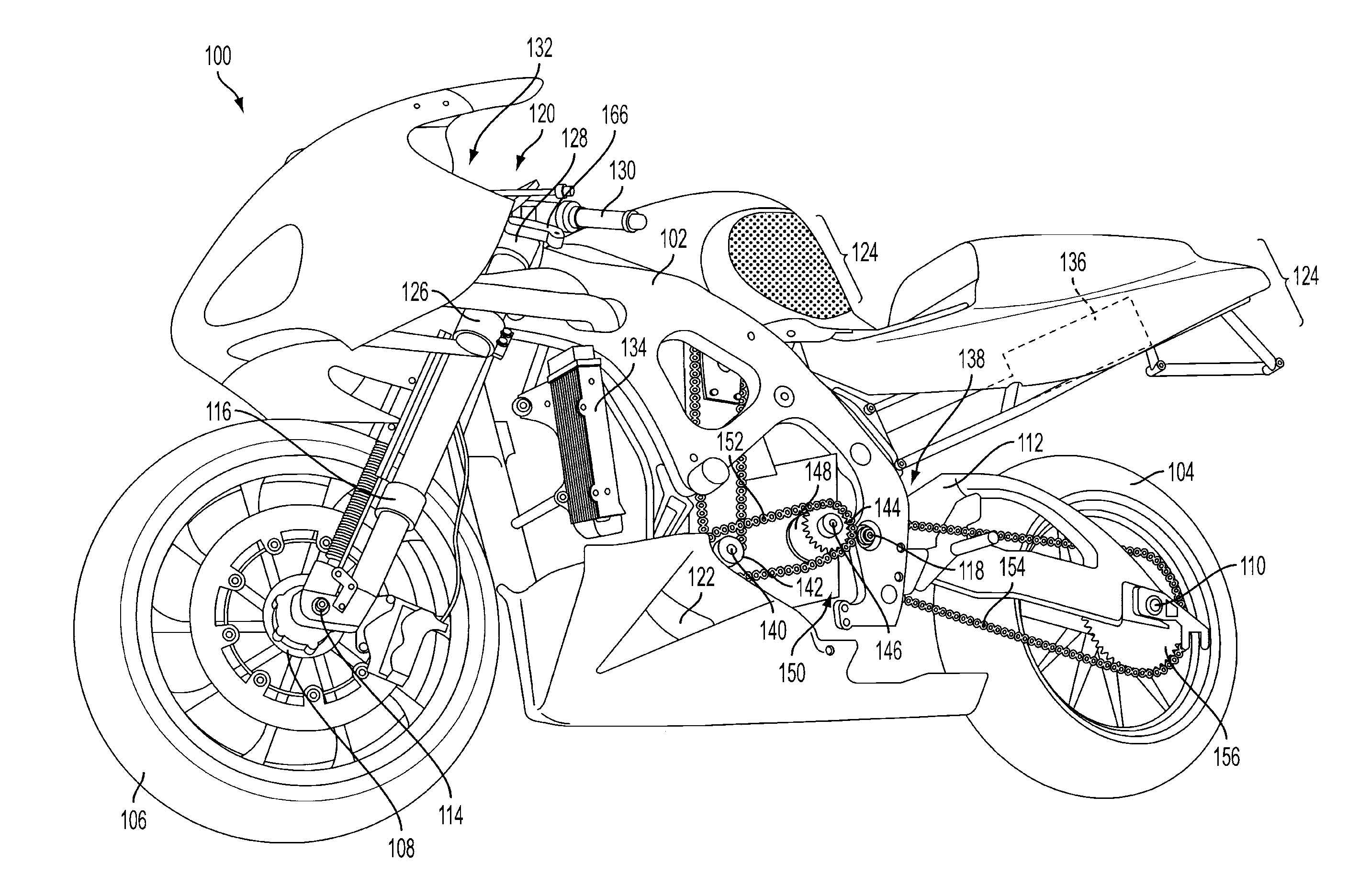
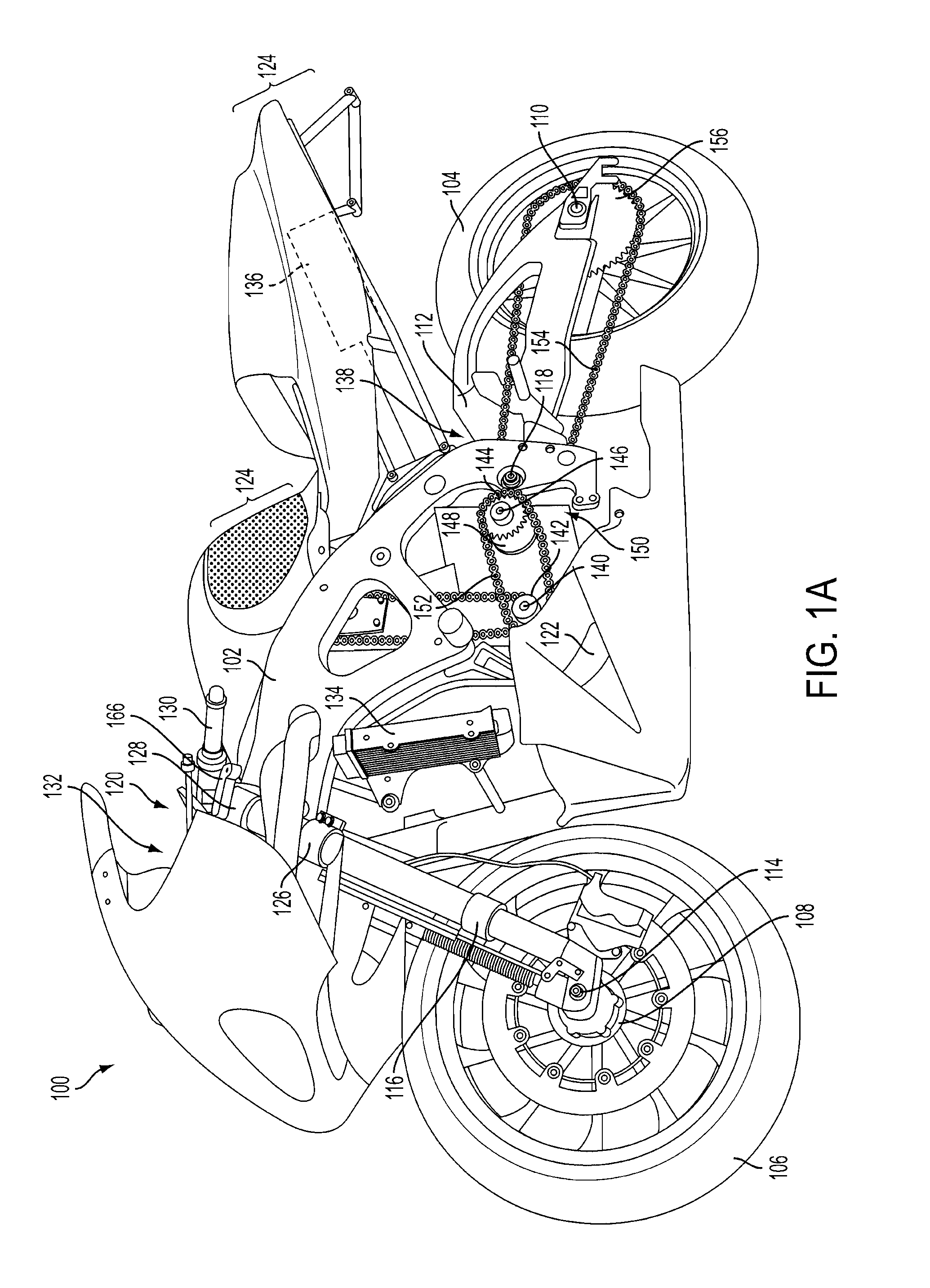
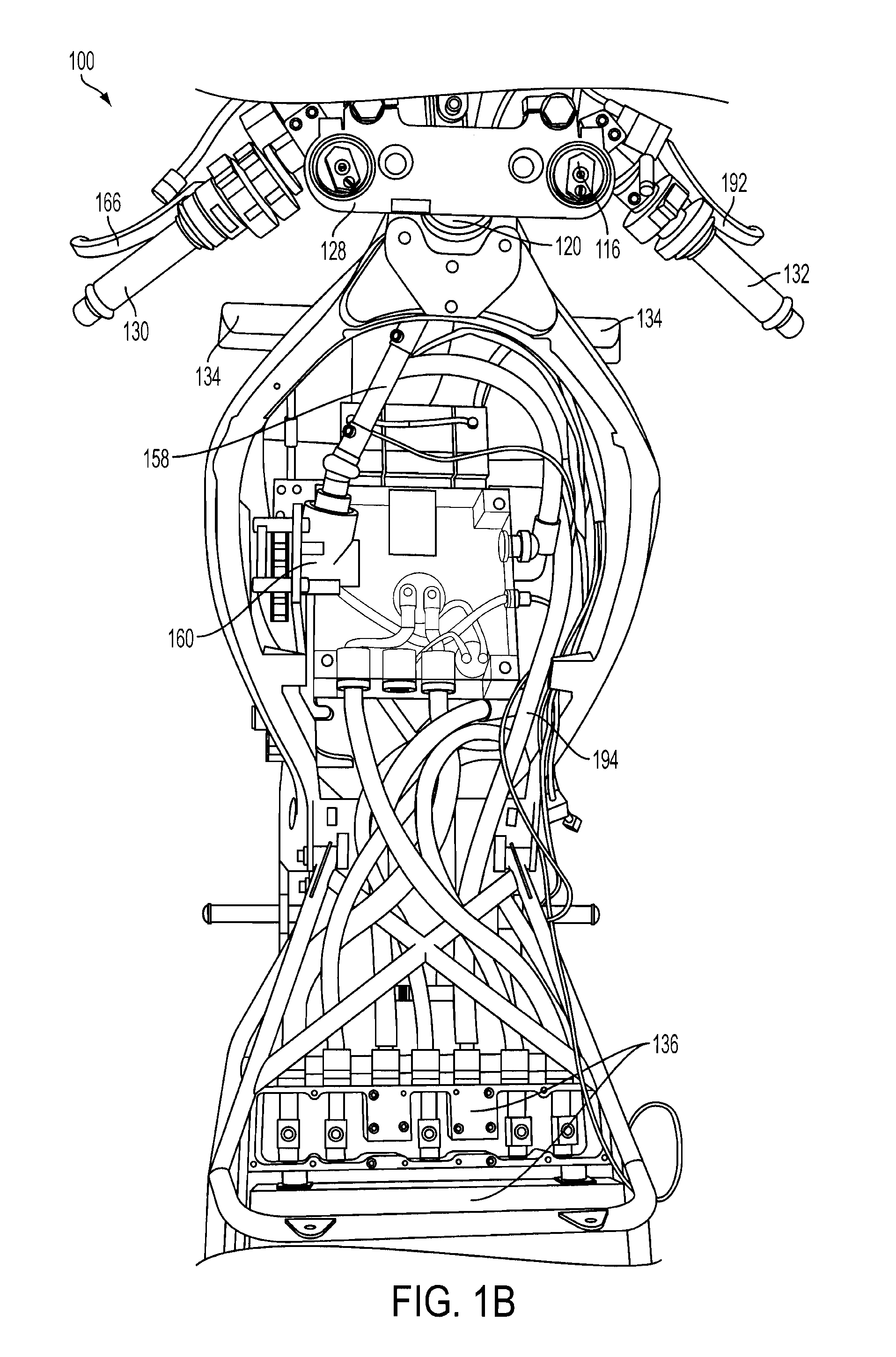
[0059]Embodiments relate to a kinetic energy recovery system and a motorcycle equipped with the same. It should be noted that for simplicity, the following paragraphs discuss embodiments relating to a motorcycle. This should not be viewed as limiting however, as the described KERS systems are designed for application with any two-wheeled or three-wheeled motorcycle and other vehicle. Accordingly, in addition to any type of motorcycle, the KERS systems described may also be applied to scooters, mopeds, and other two-wheel or three-wheel motorized bikes or trikes.

[0060]The energy recovery system according to exemplary embodiments may comprise a mechanical system, a hydraulic system, or a combination thereof. The mechanical system will be referred to as the mechanical KERS system. The hydraulic system will be referred to as the hydraulic KERS system.

[0061]Ex...


PUM


Abstract

A kinetic energy recovery system (“KERS system”) and motorcycle equipped with the same is disclosed. The KERS system may be mechanical, hydraulic, or a combination thereof. In an embodiment, motorcycle includes a rear wheel, an electric motor, a motor shaft, and a front wheel equipped with a wheel hub that includes a sprag clutch. The motor shaft can be fitted with a motor drive sprocket that drives a jackshaft chain that in turn drives a jackshaft input sprocket that is fitted to the jackshaft. Jackshaft input sprocket may be installed in conjunction with a sprag clutch that allows the rear wheel to free wheel during coasting while the front wheel KERS system is engaged. The motor harvests kinetic energy from the front wheel without simultaneously powering the rear wheel while the use of a geared dead zone allows the front and rear wheels to not lock together to improve safety.

Description

BACKGROUND OF THE INVENTION[0001]1. Field of the Invention[0002]The present invention relates to a system and method for energy recovery using the front wheel of a vehicle.[0003]2. Discussion of the Related Art[0004]Electric and hybrid powered vehicles offer a means of transportation that emit substantially no pollutants and produce little noise. These features are especially important at a time when such pollution has become a major concern. Although major advances have been made in electric and hybrid powered automobiles, the same cannot be said for two-wheeled and three-wheeled vehicles such as motorcycles, scooters, mopeds, and trikes, hereinafter referred to as “motorcycle(s)”.[0005]Motorcycles have a wide variety of uses and the potential to positively impact society and the environment through reduction of congestion and pollution in addition to other benefits arising from their propagation. Gasoline burning versions of these vehicles are used for recreational purposes, as a ...

Claims


Application Information

Patent Timeline
Patent Type & Authority Applications(United States)
IPC IPC(8): B60L11/00
CPCB60L7/18B60L15/2045B60L2200/12B62K11/04B60L11/002B62M7/02B62M23/02Y02T10/7283B62K2204/00Y02T10/72B60L50/90B62M19/00Y02T10/64
Inventor YATES, III, WILLIAM M.INGRAM, BENJAMIN T.
Owner W MORRISON CONSULTING GRP
Learn More