Cable connector

a technology of cable connectors and connectors, applied in the direction of electrical apparatus, connection, coupling device connection, etc., can solve the problems of unintentional unfavorable fpc out of the contacts, and difficulty in large-scale rotation of the lock member with a small amount of force, and achieve the effect of high lock retention ability

Inactive Publication Date: 2013-08-29
KYOCERA CORP
View PDF9 Cites 4 Cited by
  • Summary
  • Abstract
  • Description
  • Claims
  • Application Information

AI Technical Summary

Benefits of technology

[0025]Furthermore, since the cable connector is provided with the pair of lock members which rotate mutually independent of each other, even if an unintentional external force is applied against one of the lock members in a locked state, the other loc...

Problems solved by technology

However, since the inserted FPC is only retained by the contacting pressure of the contacts (contact pieces), if an unintentional strong external force is applied on the FPC in a pulling-out (removal) direction, the FPC can come out of the contacts unexpectedly.
However, if the connector is made thinner so as to have a low profile, it becomes difficult to rotate the lock member by a large amount with a small amount of force since the axial length...

Method used


Image

  • Cable connector
  • Cable connector
  • Cable connector

Examples


first embodiment

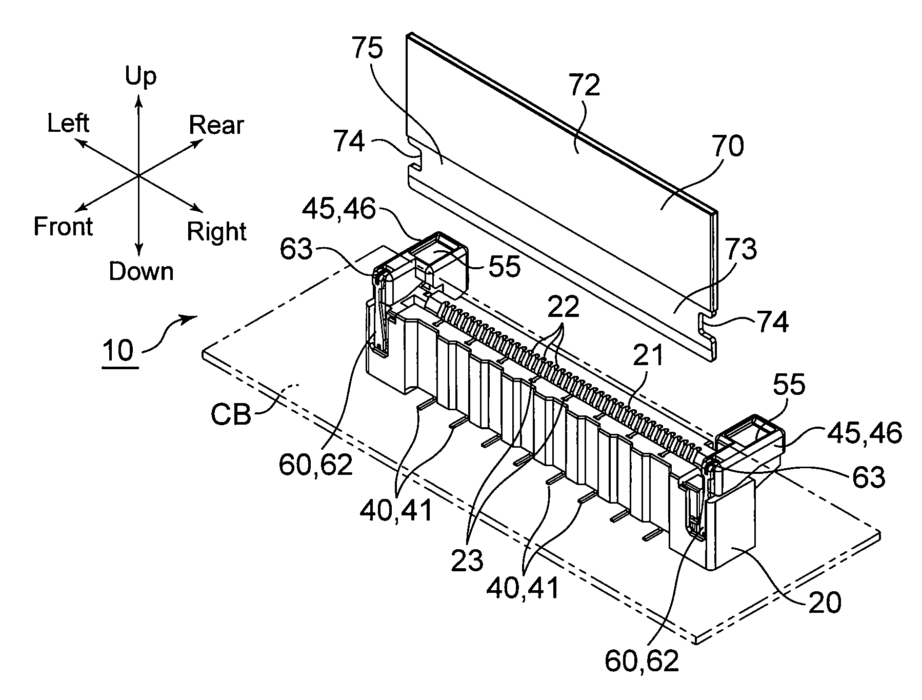
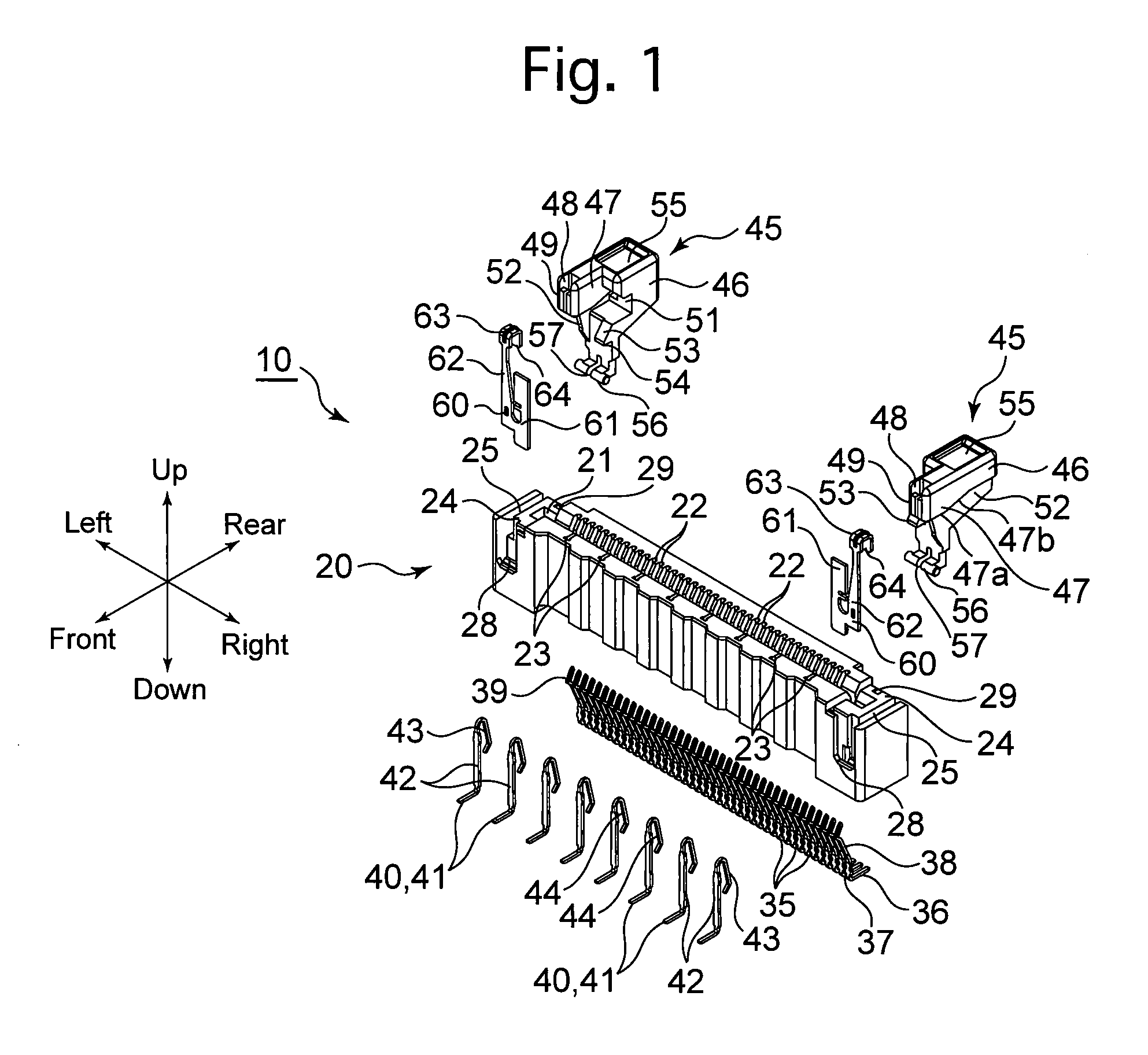
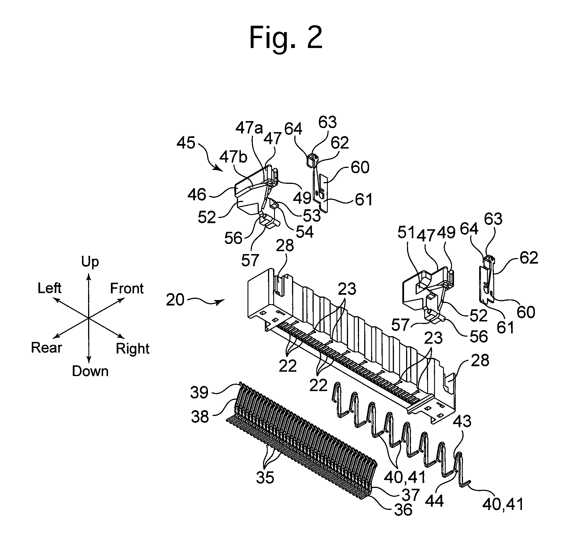
[0061]the present invention will be hereinafter discussed with reference to FIGS. 1 through 21. Note that the “upward”, “downward”, “left”, “right”, “forward” and “rearward” directions are based on the directions of the arrows that are indicated in the drawings.

[0062]The cable connector of the first embodiment is a so-called “straight” (ST) FPC connector 10 in which a cable (FPC 70) is inserted in a direction orthogonal to a circuit board CB, onto which the connector is installed; e.g., the connector can be installed onto a circuit board CB (see FIGS. 3, 4, 8, 12, 15 and 19) which is provided inside a car navigation system or an audio device installed in an automobile (vehicle), or office automation equipment (e.g., a photocopier machine, or a multifunction printer provided with photocopying and facsimile functions, etc.). The FPC connector 10 is provided with, as major components thereof, an insulator 20, signal contacts 35, ground contacts 40, a pair of lock members 45, and a pair...

second embodiment

[0096]The cable connector of the second embodiment is a so-called “right-angle” (RA) FPC connector 80 which inserts a cable (FPC 70) in a direction parallel to a circuit board CB, onto which a connector is installed. The FPC connector 80 is provided with, as major components thereof, a pair of lock-member biasing springs 60, an insulator 81, signal contacts 90, ground contacts 92, and a pair of lock members 94.

[0097]The insulator 81, which is bilaterally symmetrical in shape, is formed out of the same material as that of the insulator 20 via injection molding. The insulator 81 is provided with an FPC insertion groove (cable insertion groove) 82 which is formed in the front surface of the insulator 81, forty (40) signal-contact insertion grooves 83 formed on the upper surface on the FPC insertion groove 82, eight (8) ground-contact insertion grooves 84 formed in the undersurface of the FPC insertion groove 82, a pair of left and right spring support grooves 85 formed in the upper sur...


PUM


Abstract

A cable connector includes an insulator, signal contacts supported in the insulator, wherein the signal contacts come in contact with the cable when the cable is inserted into the insulator, a pair of lock members which are rotatable between a locked position and an unlocked position, and springs supported on the insulator, wherein the springs retain the locked position and allow rotation of the lock members to the unlocked position by elastic deformation of the springs. Each spring includes a base-plate portion supported on the insulator, an elastically deformable portion extending from the base-plate portion, an end-extending portion extending from an end of the elastically deformable portion, and an engaging portion which engages with an associated lock member to integrate the spring with the associated the lock member.

Description

CROSS REFERENCE TO RELATED APPLICATION[0001]The present invention is related to and claims priority of the following co-pending application, namely, Japanese Patent Application No. 2012-041026 filed on Feb. 28, 2012.FIELD OF THE INVENTION[0002]The present invention relates to a cable connector.BACKGROUND OF THE INVENTION[0003]A so-called Non-ZIF (Zero Insertion Force) connector is known as an example of an FPC connector in which an insertion force is necessary when a FPC is inserted into the connector.[0004]A Non-ZIF type of FPC connector generally has a structure in which an insertion and retaining of an FPC is carried out in a single action, so that by setting a distance (space) between a pair of contacts (or a distance (space) between a pair of contact pieces provided in a single contact) to be slightly narrower (smaller) than the thickness of the FPC, upon an FPC being inserted into the pair of contacts, a predetermined amount of contacting pressure is applied from the pair of c...

Claims


Application Information

Patent Timeline
IPC IPC(8): H01R13/627
CPCH01R13/627H01R12/79H01R12/774H01R12/77H01R13/639
Inventor KITAGAWA, NAOKI
Owner KYOCERA CORP
Why Eureka
Try Eureka