
Optical sensor and image forming apparatus

a technology of optical sensors and image forming apparatuses, which is applied in the direction of electrographic process apparatus, instruments, electrographic process, etc., can solve the problems of cumbersome input for users, uneven coloring, and large impact on image quality in recording media, so as to achieve the effect of not causing a large size device or high cos

Inactive Publication Date: 2013-08-22
RICOH KK
View PDF45 Cites 33 Cited by
  • Summary
  • Abstract
  • Description
  • Claims
  • Application Information

AI Technical Summary

Benefits of technology

The present invention provides an optical sensor that can precisely detect and identify objects without being too expensive or requiring a large device.

Problems solved by technology

This is because image quality in the recording medium is largely affected by the quality of material, thickness, humidity, smoothness, and coating conditions thereof.
Thus, uneven coloring occurs unless fixing is performed with proper conditions which are dependent on the recording medium.
Therefore, the user is required to have knowledge for identifying the type of paper; moreover, it is cumbersome for the user himself to input each time settings are made depending on the type of paper.
Then, if there is an error with the settings, it is not possible to obtain an optimal image.

Method used


Image

  • Optical sensor and image forming apparatus
  • Optical sensor and image forming apparatus
  • Optical sensor and image forming apparatus

Examples


Embodiment Construction

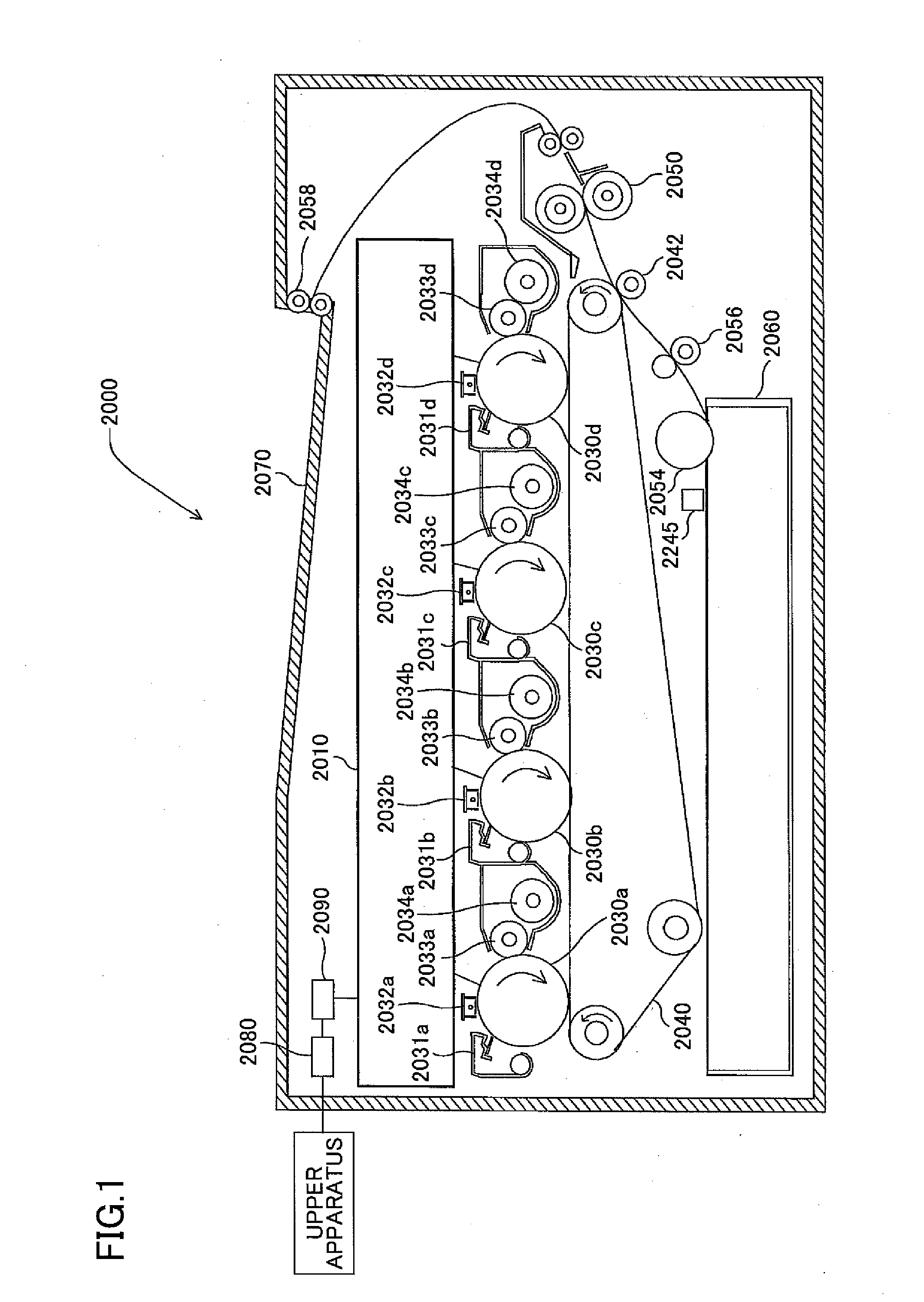
[0056]Below, one embodiment of the present invention is described based on FIGS. 1 to 14. FIG. 1 shows a schematic configuration of a color printer 2000 according to one embodiment.

[0057]This color printer 2000, which is a tandem-type multi color printer which forms a full-color image by overlapping four colors (black, cyan, magenta, yellow), includes an optical scanning apparatus 2010; four photoconductor drums (2030a, 2030b, 2030c, 2030d); four cleaning units (2031a, 2031b, 2031c, 2031d); four charging apparatuses (2032a, 2032b, 2032c, 2032d); four developing rollers (2033a, 2033b, 2033c, 2033d); a transfer belt 2040; a transfer roller 2042; a fixing apparatus 2050; a paper-feeding roller 2054; a paper-discharging roller 2058; a paper-feeding tray 2060; a paper-discharging tray 2070; a communications control apparatus 2080; an optical sensor 2245; and a printer control apparatus 2090, which exercises control of the above-described respective elements.

[0058]The communications contr...


PUM


Abstract

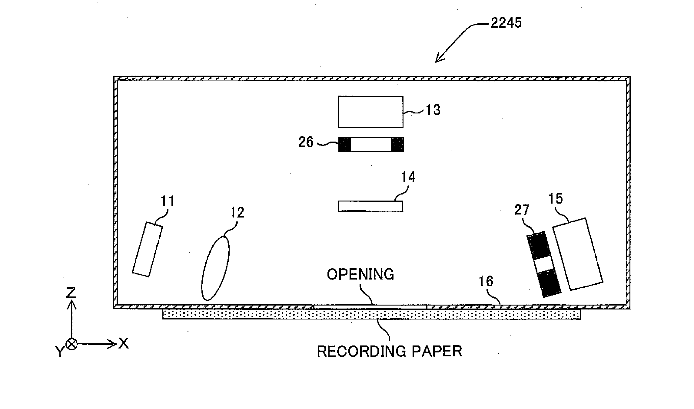
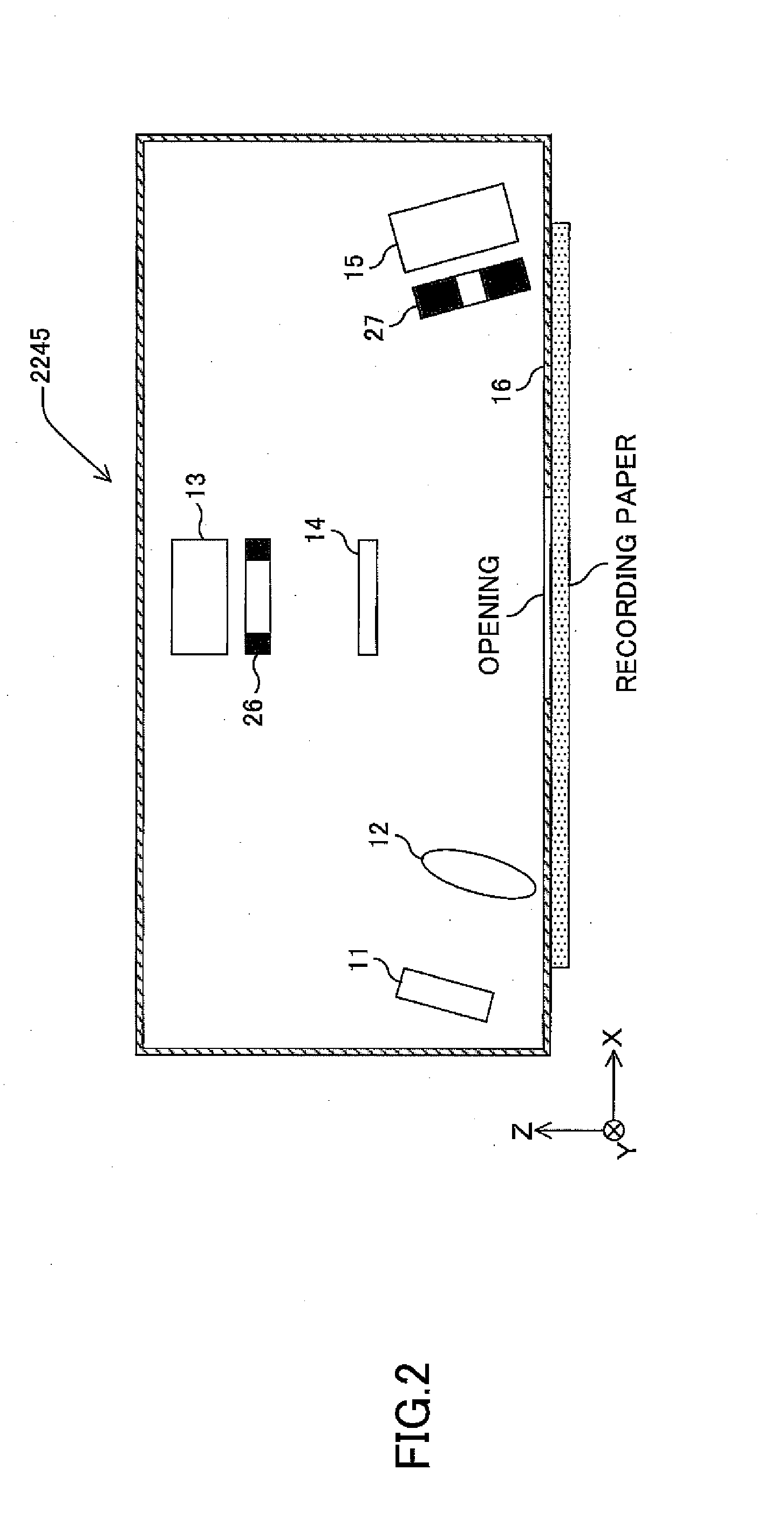
An optical sensor is disclosed, including an irradiating system; a first photodetecting system including a first photodetector which is arranged on an optical path of a light which is specularly reflected from a subject; a second photodetecting system including an optical element which is arranged on an optical path of a light which is diffuse reflected from the subject within an incident face in the subject and which separates a linearly polarized component in a second polarizing direction which is orthogonal to a first polarizing direction and a second photodetector which receives a light separated by the optical element; and a restricting member which is arranged on an optical path of an incident light with respect to at least one of the first photodetector and the second photodetector and which restricts a light receiving range in the at least one photodetector.

Description

TECHNICAL FIELD[0001]The present invention relates to optical sensors and image forming apparatuses and particularly to optical sensors which are suitable for specifying an object and image forming apparatuses which include the optical sensors.BACKGROUND ART[0002]An image forming apparatus such as a digital copying machine, a laser printer, etc., forms an image by transferring a toner image onto a surface of a recording medium including printing paper, and heating and pressurizing at predetermined conditions to fix the toner image. What need to be taken into account in image forming are conditions of pressure and thermal dose at the time of fixing. In particular, in order to conduct high quality image forming, it is necessary to set fixing conditions individually according to the recording medium.[0003]This is because image quality in the recording medium is largely affected by the quality of material, thickness, humidity, smoothness, and coating conditions thereof. For example, wit...

Claims


Application Information

Patent Timeline
IPC IPC(8): G03G15/00G01N21/55
CPCG03G15/0189G03G15/5029G03G2215/2074
Inventor HOSHI, FUMIKAZUSUGAWARA, SATORUISHII, TOSHIHIROOBA, YOSHIHIRO
Owner RICOH KK
Learn More