Air-Conditioning Apparatus and Configuration of Installation of Same

a technology of air conditioning apparatus and configuration, which is applied in the direction of indirect heat exchangers, lighting and heating apparatus, heating types, etc., can solve the problems of poor air circulation in the indoor space, long ducts, and low comfortability, so as to reduce the torque of the fan motor, shorten the length of each duct, and reduce the effect of ventilation resistan

Active Publication Date: 2013-08-22
MITSUBISHI ELECTRIC CORP
View PDF5 Cites 11 Cited by
  • Summary
  • Abstract
  • Description
  • Claims
  • Application Information

AI Technical Summary

Benefits of technology

The present invention relates to an air-conditioning apparatus that can improve the comfortability of a room, save energy, and reduce noise. The apparatus has a unique design that allows for efficient distribution of conditioned air throughout the room. It can connect a greater number of ducts to the body casing, which increases the outlet ports and reduces the need for additional outlet ports. This design also reduces ventilation resistance, reduces power consumption, and prevents short cycles that may hinder air conditioning. Overall, the air-conditioning apparatus described in this patent provides improved comfortability, energy savings, and low noise.

Problems solved by technology

Accordingly, since air tends to stagnate in the area of the room far from the body casing, problems such as poor circulation of the air in the indoor space and low comfortability (not being able to turn the room into a comfortable environment) are encountered.
Problems such as requiring a long duct to connect the body casing and the outlet unit and increase of ventilation resistance in the duct are associated with these cases.
As a result, in the air-conditioning apparatus described in Patent Literature 1, because ventilation resistance in the duct increases, the torque of the fan motor rotatably driving the fan to maintain the required air volume increases, and accordingly, the power consumption increases, disadvantageously leading to less energy saving (poor energy efficiency).
Moreover, the rotation speed of the fan becomes high and noise disadvantageously becomes worse.
As a result, in the air-conditioning apparatus described in Patent Literature 2, because the torque of the fan motor rotatably driving the fan to maintain the required air volume increases, the power consumption increases, disadvantageously leading to less energy saving (poor energy efficiency).
Moreover, the rotation speed of the fan becomes high and noise disadvantageously becomes worse.
In addition, because the air-conditioning apparatus described in Patent Literature 2 can be provided with only four outlet units, that is, because there are only four outlet ports that deliver conditioned air to the indoor space, the temperature difference in the room becomes large, leading to a problem such as low comfortability (not being able to turn the room into a comfortable environment).

Method used


Image

  • Air-Conditioning Apparatus and Configuration of Installation of Same
  • Air-Conditioning Apparatus and Configuration of Installation of Same
  • Air-Conditioning Apparatus and Configuration of Installation of Same

Examples


embodiment

[0031]Referring to the drawings, an air-conditioning apparatus according to the disclosure will be described below.

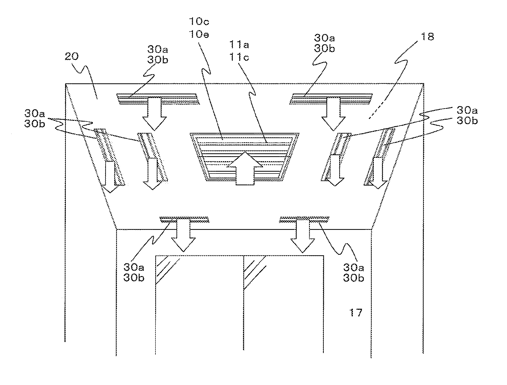
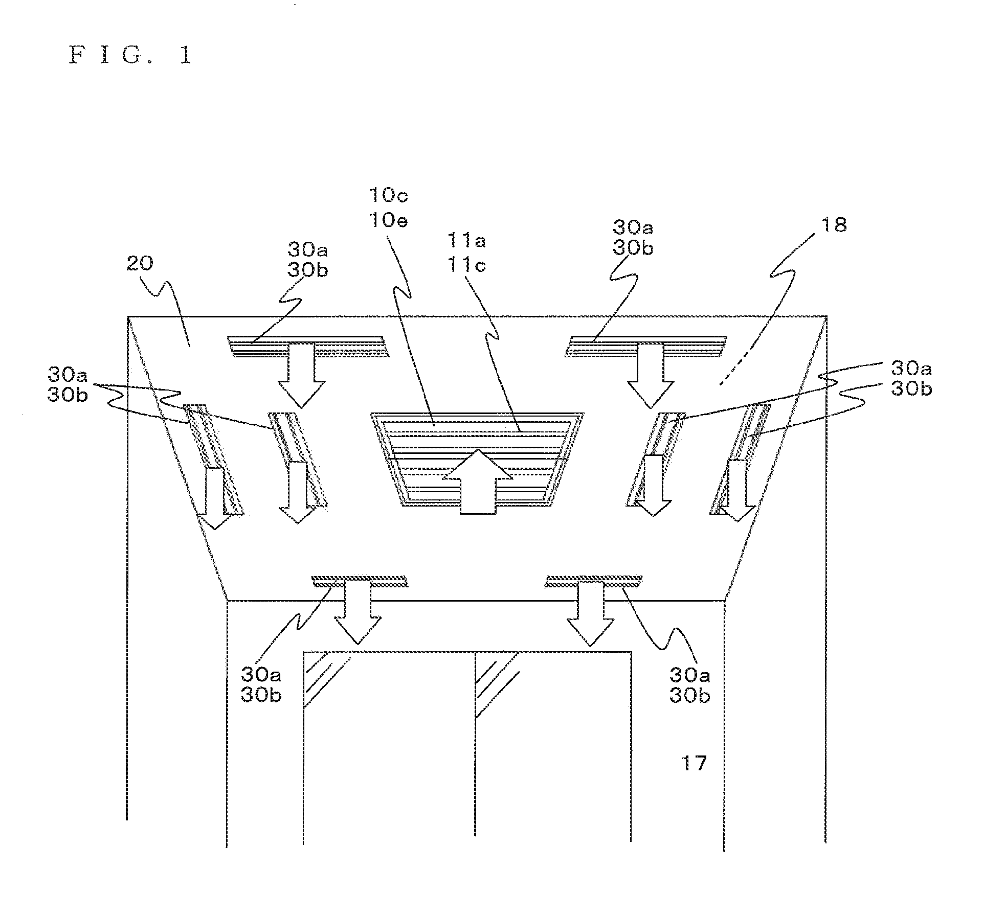
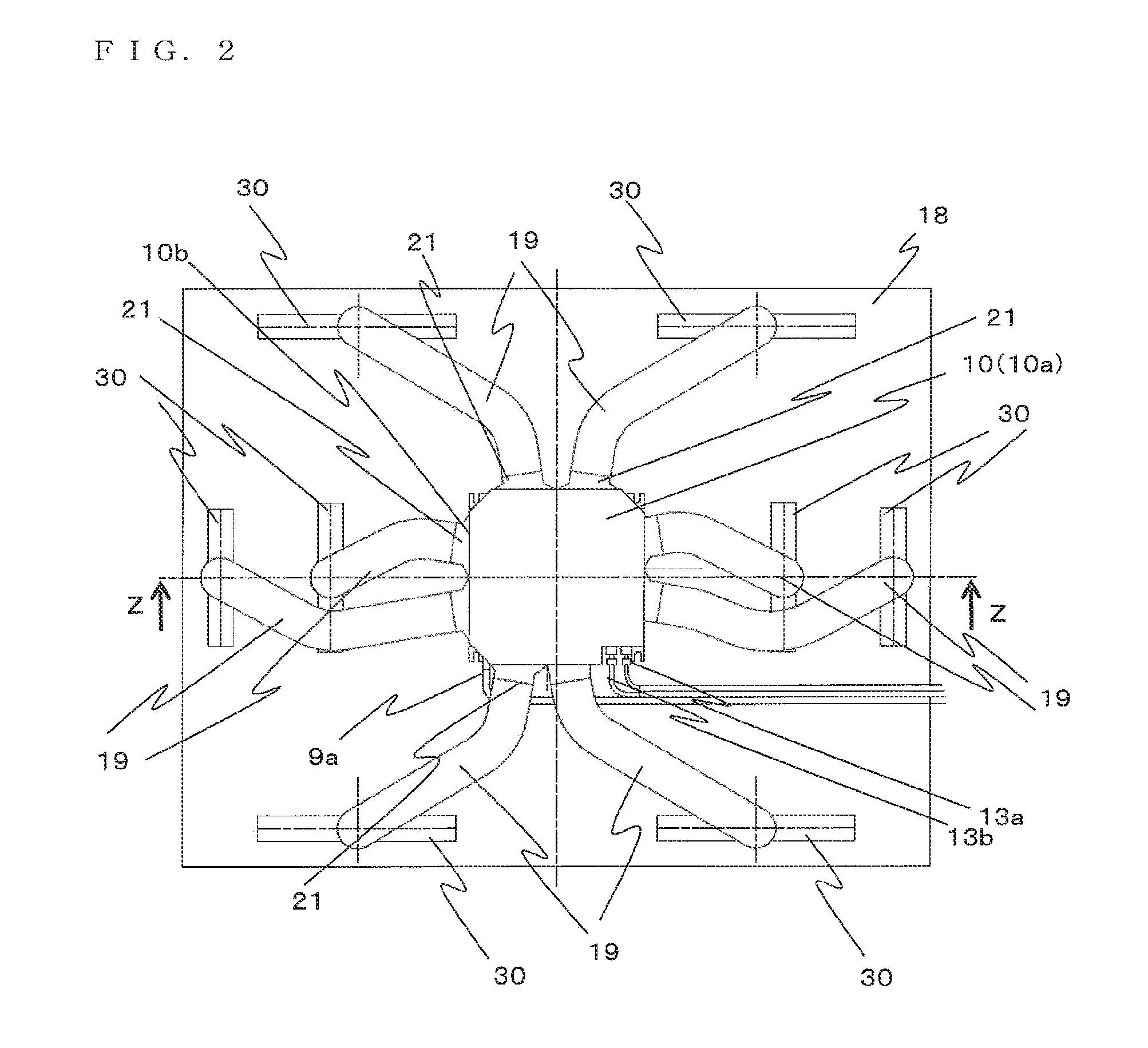
[0032]FIG. 1 is a schematic diagram (perspective view) of an installation state of an exemplary embodiment of an air-conditioning apparatus according to the disclosure viewed from inside a room. FIG. 2 is a schematic diagram (plan view) of the installation state of the air-conditioning apparatus according to the disclosure viewed from a space above a ceiling. FIG. 3 is a longitudinal sectional view taken along the line Z-Z of FIG. 2. FIG. 4 is a cross sectional view of a body casing of an indoor unit of the air-conditioning apparatus taken along a virtual plane orthogonal to a rotation shaft of a centrifugal fan (a turbo fan, for example). FIG. 5 is an arrow view taken in the direction of an arrow Y of FIG. 4. FIG. 8 is a refrigerant circuit diagram of the air-conditioning apparatus illustrated in FIG. 6.

[0033]An indoor unit 50 of an air-conditioning apparatus 100 accor...


PUM


Abstract

An air-conditioning apparatus includes a body casing of an indoor unit formed in a substantially rectangular parallelepiped shape. The body casing is formed with a body inlet port on a body bottom, and a body outlet port is formed in each body side. The body casing houses a centrifugal fan, a fan motor rotatably driving the centrifugal fan, and an indoor heat exchanger disposed so as to surround an outer periphery of the centrifugal fan in planar view. In each of the body outlet port, a joint is protrudingly provided with a body-side duct connecting portion that connects a duct thereto. Further, outlet ports are formed. The air-conditioning apparatus includes a plurality of outlet units each protrudingly provided with an outlet-side duct connecting portion that connects the duct thereto. Furthermore, at least one of the joints is formed with a plurality of the body-side duct connecting portions.

Description

FIELD OF INVENTION[0001]The present disclosure relates to an air-conditioning apparatus and a configuration of installation of the air-conditioning apparatus.BACKGROUND OF THE INVENTION[0002]Hitherto, as air-conditioning apparatuses installed in ceilings of rooms, an air-conditioning apparatus has been proposed having a duct connecting a body casing of an indoor unit, which is formed with an inlet port on the bottom side thereof and houses a fan and an indoor heat exchanger therein, to an outlet unit, which is formed with an outlet port opening downwards (in the direction from the ceiling side to the indoor space). In such a conventional air-conditioning apparatus, indoor air is drawn into the body casing and is made to exchange heat, and the conditioned air after exchanging heat is delivered to the indoor space through the outlet port of the outlet unit.[0003]As an air-conditioning apparatus having the above configuration, an air-conditioning apparatus described in Patent Literatur...

Claims


Application Information

Patent Timeline
IPC IPC(8): F28D15/00
CPCF24F1/0022F24F1/0014F24F2001/0037F24F13/0209F24F3/044F24F1/0047
Inventor IKEDA, TAKASHIBUSH, JOSEPH PAULOKAZAKI, TAKASHIKASAI, TOMOHIKO
Owner MITSUBISHI ELECTRIC CORP
Why Eureka
Try Eureka