
Deposition ring

a technology of deposition rings and rings, applied in chemical vapor deposition coatings, metal material coating processes, coatings, etc., can solve problems such as reducing service cycles, and achieve the effect of shortening service cycles and improving deformation or fracture problems

Inactive Publication Date: 2013-08-15
WELL THIN TECH
View PDF2 Cites 4 Cited by
  • Summary
  • Abstract
  • Description
  • Claims
  • Application Information

AI Technical Summary

Benefits of technology

The present invention seeks to improve the deformation or fracture problem of conventional deposition rings caused by thermal expansion and cold contraction or external stress that results in shortened service cycle. The invention achieves this through a protective member that reduces deposition of particles and the likelihood of them adhering to the wafer's back. The structure also provides greater stress resistant capability and resolves the problem of easy fracturing.

Problems solved by technology

However, the inner circumferential edge of the aforesaid deposition ring is prone to deform or fracture due to thermal expansion and cold contraction after being repeatedly used for a number of times. As a result, the service cycle is reduced.

Method used


Image

  • Deposition ring
  • Deposition ring
  • Deposition ring

Examples


Embodiment Construction

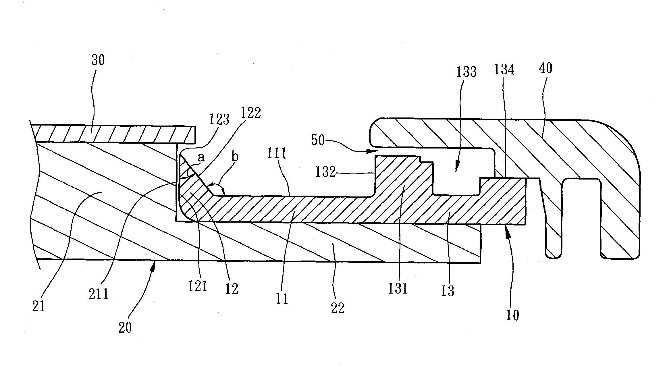
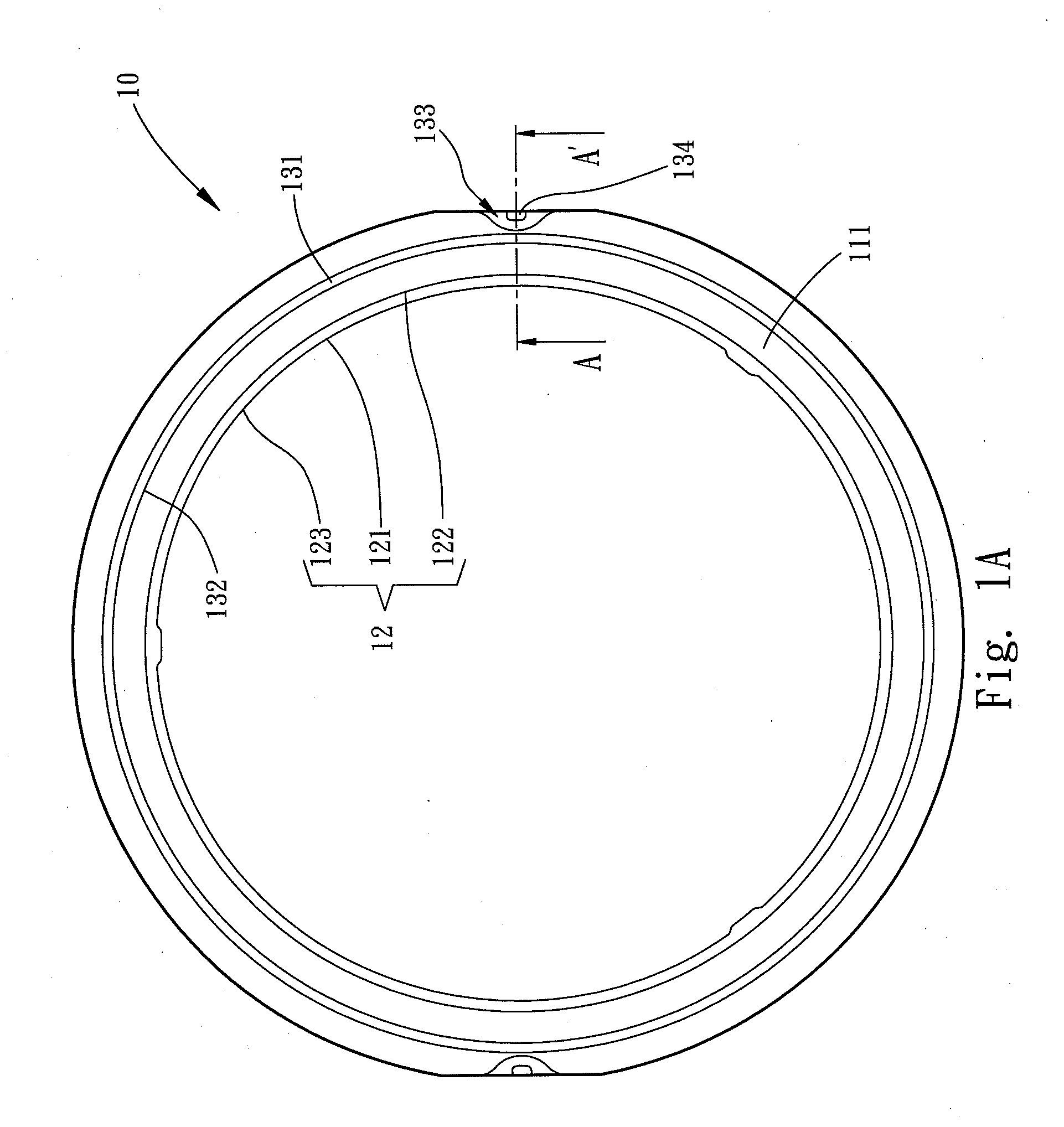
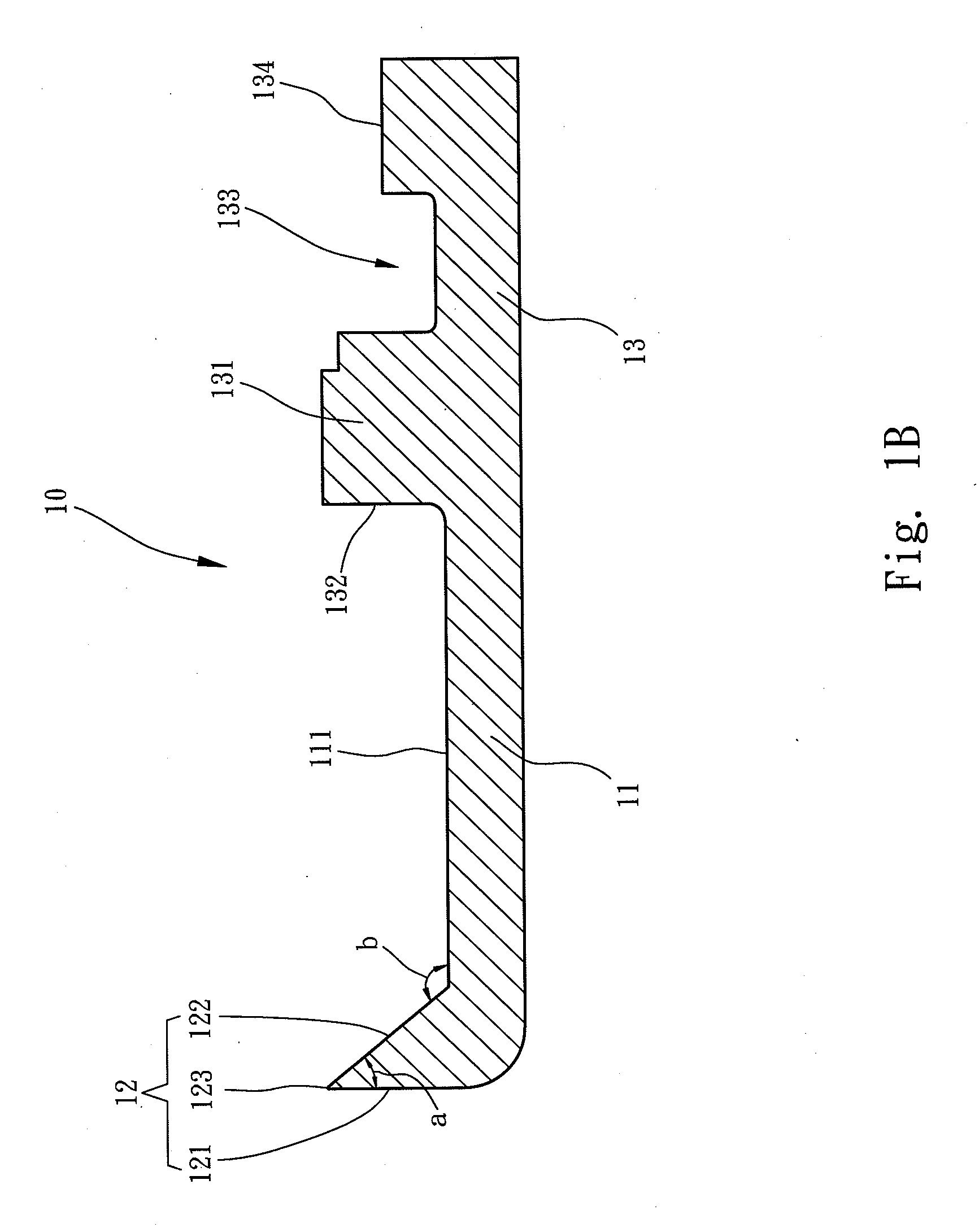
[0017]Please refer to FIGS. 1 A, 1B and 2 for a first embodiment of the invention. The invention provides a deposition ring 10 used on thin film deposition equipment. The thin film deposition equipment has a chuck 20 which includes a holding portion 21 and an extension 22 connecting to the holding portion 21. The holding portion 21 is higher than the extension 22 and has a circumferential wall 211. The chuck 21 can hold a wafer 30. The extension 22 holds the deposition ring 10. The deposition ring 10 surrounds the circumferential wall 211 and includes an inner ring 11, an outer ring 13 and a protective member 12. The inner ring 11 is adjacent to the circumferential wall 211. The outer ring 13 is connected to the outer ring 11 and is located at one side of the inner ring 11 remote from the circumferential wall 211. The protective member 12 is jutting from the inner ring 11 and includes a circumferential surface 121, a barrier surface 122 and a tip edge 123. The circumferential surfac...


PUM

PropertyMeasurementUnit
obtuse angleaaaaaaaaaa
depthaaaaaaaaaa
elevationaaaaaaaaaa

Abstract

A deposition ring is used on thin film deposition equipment which includes a chuck to hold a wafer. The deposition ring is arranged on the circumferential wall of the chuck and includes an inner ring and a protective member. The inner ring is adjacent to the circumferential wall. The protective member is jutting from the inner ring and has a circumferential surface, a barrier surface and a tip edge. The circumferential surface opposes the circumferential wall. The barrier surface and circumferential surface form an acute angle between them. The tip edge is formed between the circumferential surface and barrier surface. Through the protective member, the probability of adhering deposition particles to the back of the wafer is greatly reduced. The protective member is formed in a structure with a gradually increasing bottom, hence can provide higher stress resistant capability and overcome the easy fracturing problem in the conventional techniques.

Description

FIELD OF THE INVENTION[0001]The present invention relates to a semiconductor equipment component and particularly to a deposition ring.BACKGROUND OF THE INVENTION[0002]Semiconductor industry is very much thriving these days. Thin film deposition technique is a manufacturing technique widely used in the semiconductor industry. The thin film deposition technique mainly can be divided mainly into physical vapor phase deposition by employing physical phenomenon and chemical vapor phase deposition by employing chemical reactions. It mainly aims to perform a deposition process in thin film deposition equipment.[0003]The thin film deposition equipment employs an electrostatic chuck to hold a wafer intend for thin film deposition. The electrostatic chuck holds a deposition ring at the circumferential wall thereof to prevent deposition particles from adhering to the surface of the chuck, thereby to save cleaning time and cost, and improve production yield of thin film deposition.[0004]For in...

Claims


Application Information

Patent Timeline
Patent Type & Authority Applications(United States)
IPC IPC(8): C23C16/458
CPCC23C16/458C23C16/4585C23C16/4401
Inventor CHEN, BEN
Owner WELL THIN TECH
Learn More