
DC power supply apparatus

Active Publication Date: 2013-08-08
SAMSUNG ELECTRONICS CO LTD +1
View PDF11 Cites 11 Cited by
  • Summary
  • Abstract
  • Description
  • Claims
  • Application Information

AI Technical Summary

Benefits of technology

This patent aims to improve the safety, efficiency, and reliability of electronic devices that use DC power. The text describes a method to reduce power loss by applying the DC power through a diode and then using a switch to operate the load. This reduces the loss caused by voltage drops and internal resistance of the diode, resulting in more efficient power utilization. Overall, this patent helps to make electronic devices more effective and reliable.

Problems solved by technology

If the polarity of the DC power supply apparatus connected to the input of the commercial power supply is changed, not only the load may fail to operate, but also the DC power supply apparatus may burn out.
That is, since most electronic devices are equipped with an electrolytic capacitor at the input of the power supply apparatus, and such electrolytic capacitor is at risk of damage or explosion when the power having a reverse polarity is applied to the electrolytic capacity, it is imperative to determine the exact input polarity particularly when the supply of the DC power is introduced for household use.
In a case when the input polarity is to be corrected by using the diode rectifier, however, since two diodes in the diode rectifier are conducted at all times, a loss caused by a drop of the voltage of the diode and a loss caused by an internal resistance of the diode occur.
In particular, the correcting of a polarity using the diode rectifier may cause inefficient power consumption of a battery of a mobile digital device, and furthermore, may decrease the overall performance of the mobile digital device.

Method used


Image

  • DC power supply apparatus
  • DC power supply apparatus
  • DC power supply apparatus

Examples


Embodiment Construction

[0057]Reference will now be made in detail to the embodiments of the present disclosure, examples of which are illustrated in the accompanying drawings, wherein like reference numerals refer to like elements throughout.

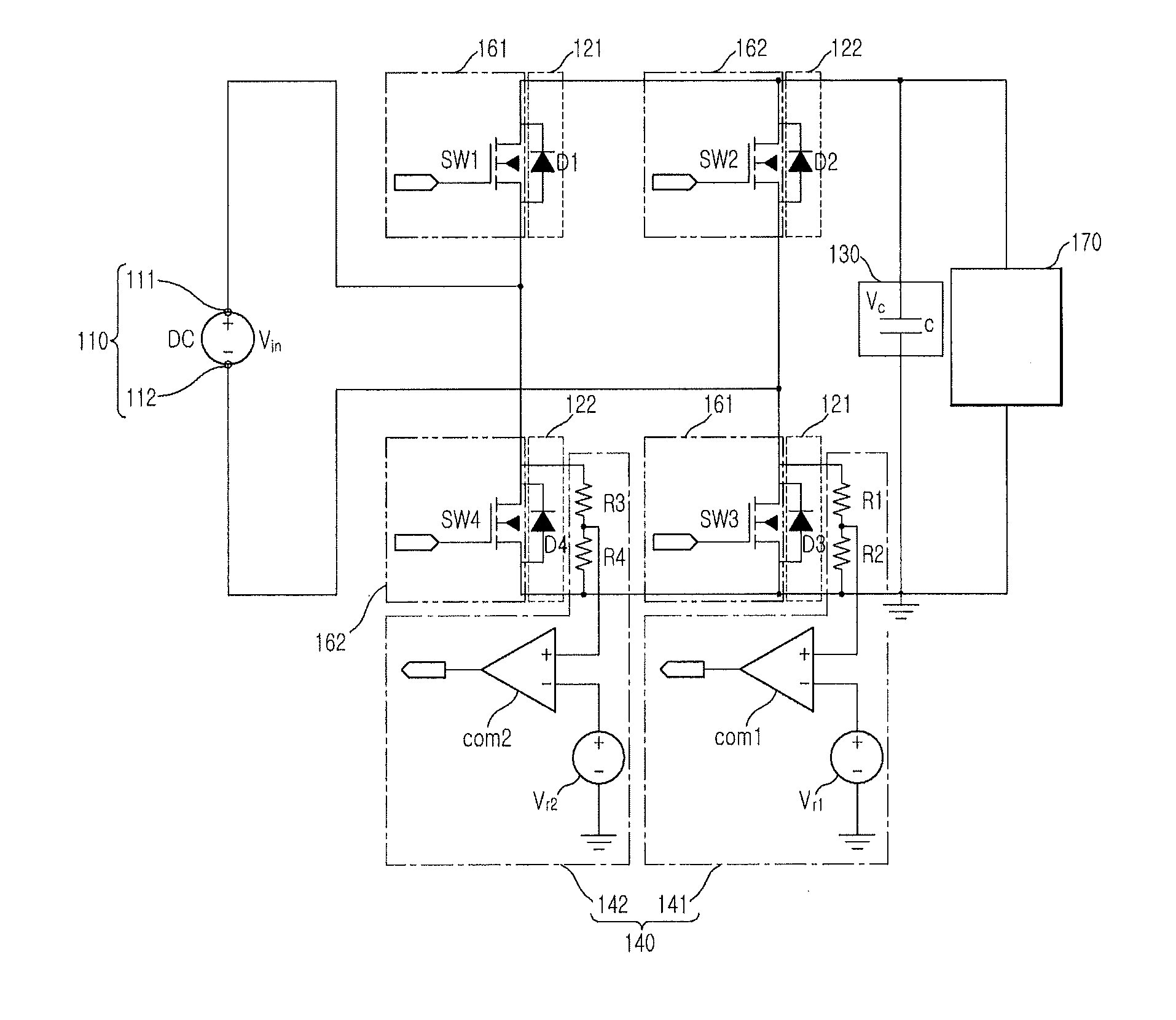
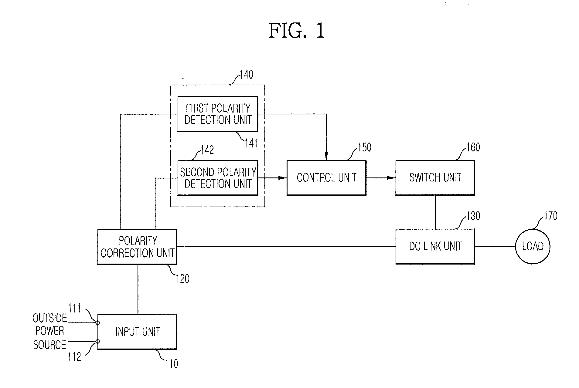
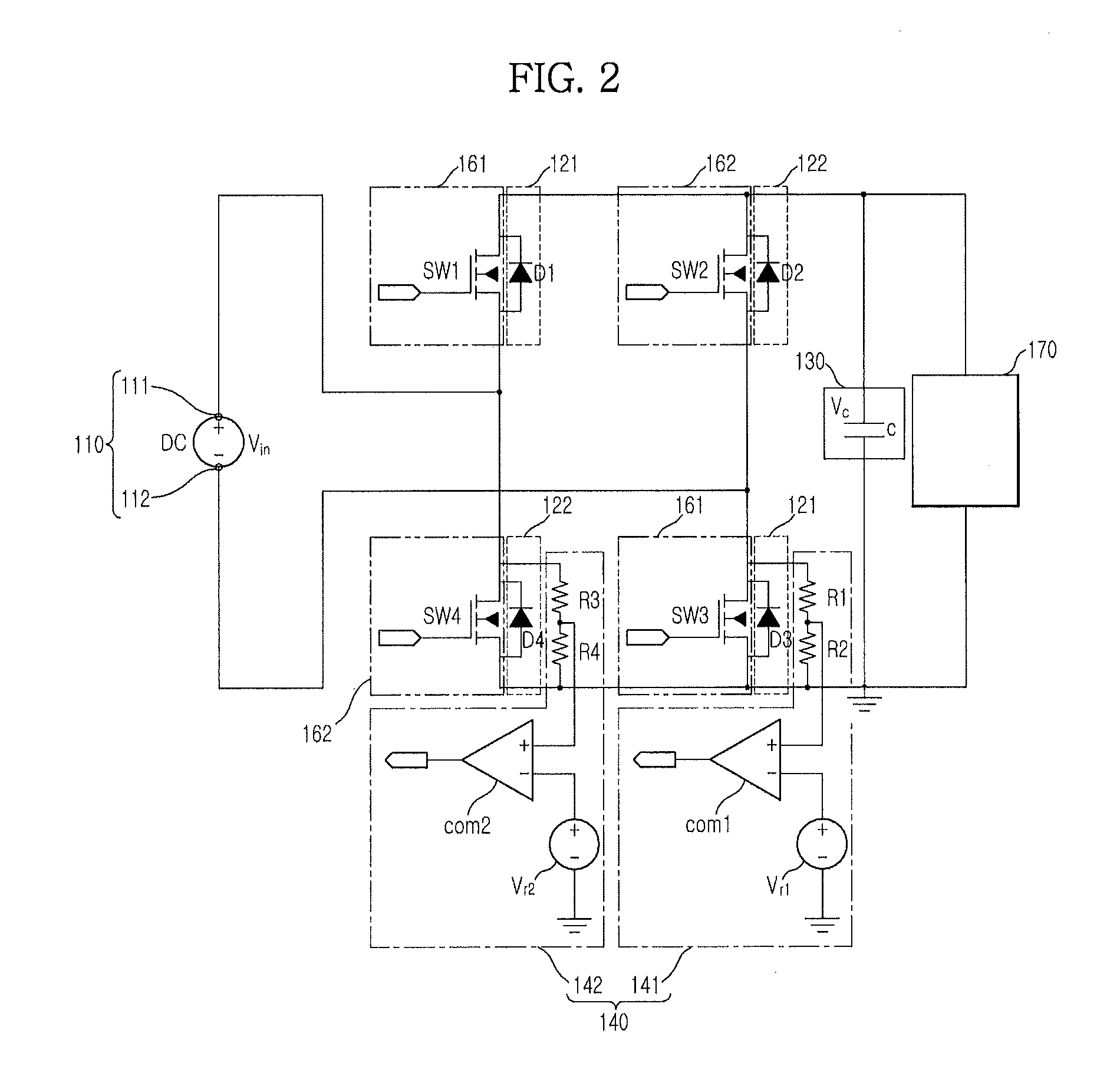
[0058]FIG. 1 is a block diagram illustrating a DC power supply apparatus in accordance with one embodiment of the present disclosure. The DC power supply apparatus configured to supply a DC power to a load 170 includes an input unit 110, a polarity correction unit 120, a DC link unit 130, a detection unit 140, a control unit 150, and a switch unit 160.

[0059]The DC power supply apparatus may further include a resistor configured to prevent an excess current from flowing at the polarity correction unit 120 and the DC link unit 130.

[0060]The input unit 110 is connected to DC power source terminals of outside to receive a DC power of outside, and conveys the DC power input to the load 170.

[0061]Such an input unit 110 includes a first terminal 111 and a second terminal 112...


PUM


Abstract

A direct current (DC) power supply apparatus includes an input unit configured to receive an outside DC power; a plurality of polarity correction units configured to correct the polarity of the outside DC power; a plurality of switch units installed to correspond to each of the plurality of polarity correction units; a detection unit configured to detect a flow of current of the plurality of polarity correction unit; and a control unit configured to determine a polarity correction unit, at which current of DC power flows, among the plurality of correction units based on a detection signal of transmitted from the detection unit, and control the switch unit corresponding to the determined polarity correction unit at an ON position such that the current of DC power flows through the switch unit which is controlled at the ON position.

Description

CROSS-REFERENCE TO RELATED APPLICATIONS[0001]This application claims the benefit of Korean Patent Application No. 10-2012-0011427, filed on Feb. 3, 2012 in the Korean Intellectual Property Office, the disclosure of which is incorporated herein by reference.BACKGROUND[0002]1. Field[0003]Embodiments of the present disclosure relate to a DC power supply apparatus configured to correct an input polarity of a DC power.[0004]2. Description of the Related Art[0005]A DC power supply apparatus originated from a digital apparatus and an Internet data center (IDC), due to an increasing efficiency as a result of a declining power conversion process, an easy link with an uninterrupted power supply apparatus, and an efficient link with new regeneration energy and a charging system for electric vehicles, is being considered for expansion for household use.[0006]As such, the DC power supply apparatus having a direct current as input power is required to be exactly connected with a positive (+) end ...

Claims


Application Information

Patent Timeline
IPC IPC(8): G05F5/00
CPCH02H11/002G05F5/00Y02E60/10H01M10/48G01R19/00H02J7/00
Inventor JIN, HYUN CHEOLKIM, SUN JINSEO, HAN SOLSHIN, SEUNG MINLEE, BYOUNG KUKJEON, JOON YOUNG
Owner SAMSUNG ELECTRONICS CO LTD
Learn More