
Cyclic adsorption process using centrifugal compressors

a technology of centrifugal compressor and adsorption system, which is applied in the direction of separation processes, machines/engines, mechanical equipment, etc., can solve the problems of not realizing power advantages, and achieve the effect of rapid reduction of head pressure, and minimizing the adverse condition of stonewall

Active Publication Date: 2013-08-08
PRAXAIR TECH INC
View PDF0 Cites 0 Cited by
  • Summary
  • Abstract
  • Description
  • Claims
  • Application Information

AI Technical Summary

Benefits of technology

The present invention provides a method to improve the power efficiency of a cyclic adsorption process using centrifugal machines instead of conventional positive displacement machines. By adjusting the process cycle time and minimizing the adverse condition of stonewall, the efficiency of the centrifugal machines can be more fully realized. The method involves replacing the positive displacement machine with a variable speed centrifugal machine, operating it under acceleration and deceleration conditions adjusted to the steps, adsorber vessel size, and process conditions employed. The technical effects of this invention include higher power efficiency and reduced energy consumption in the adsorption process.

Problems solved by technology

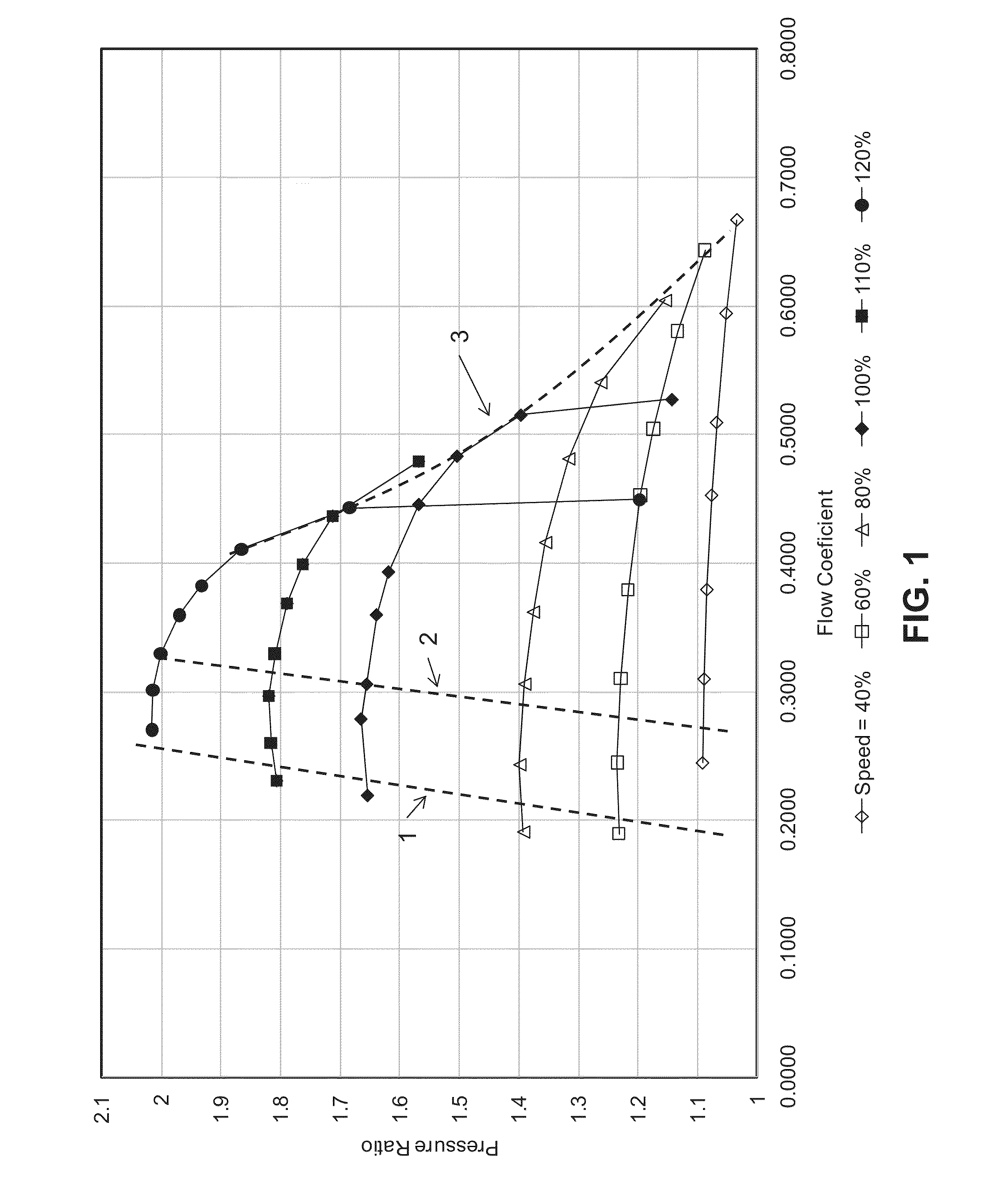
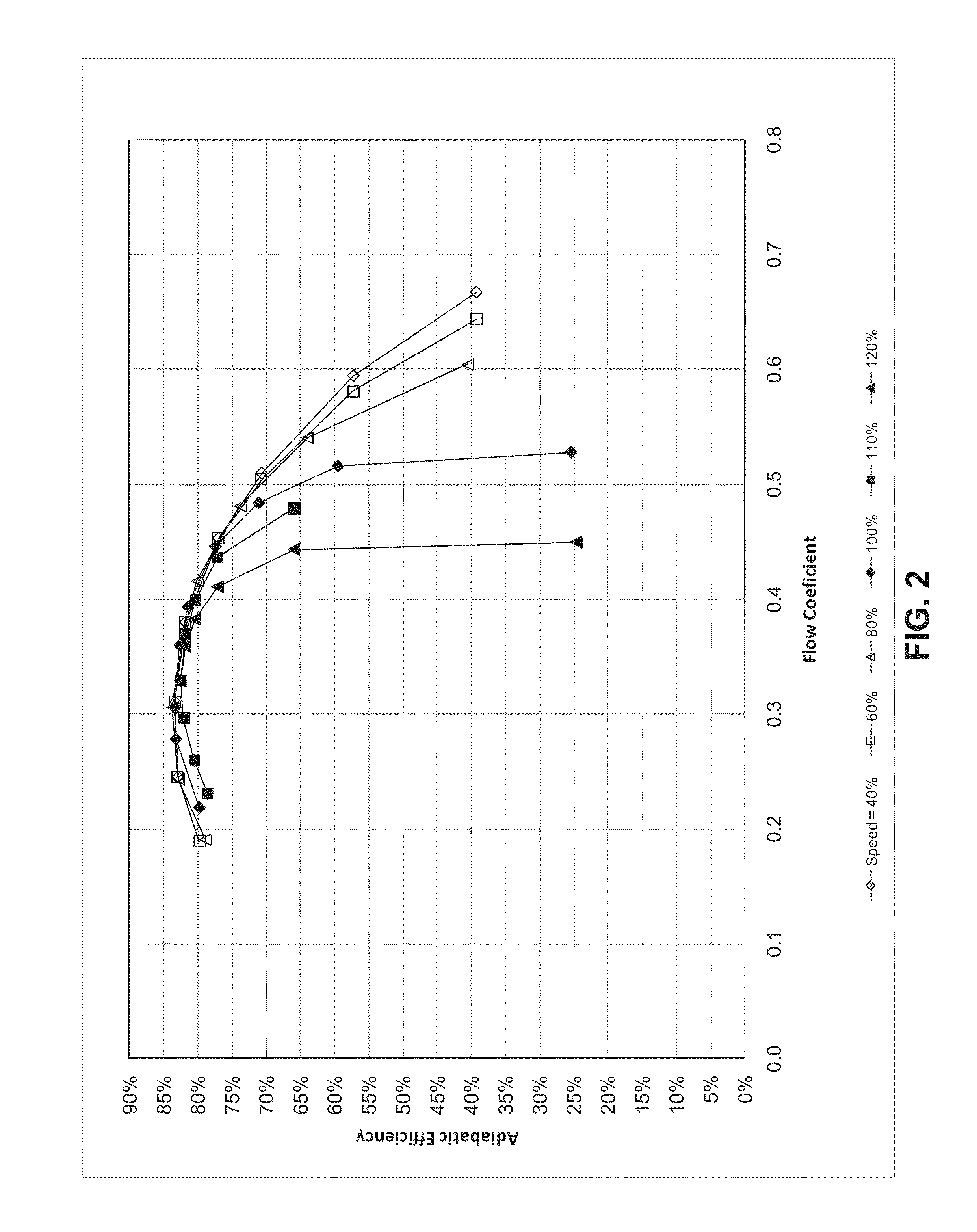
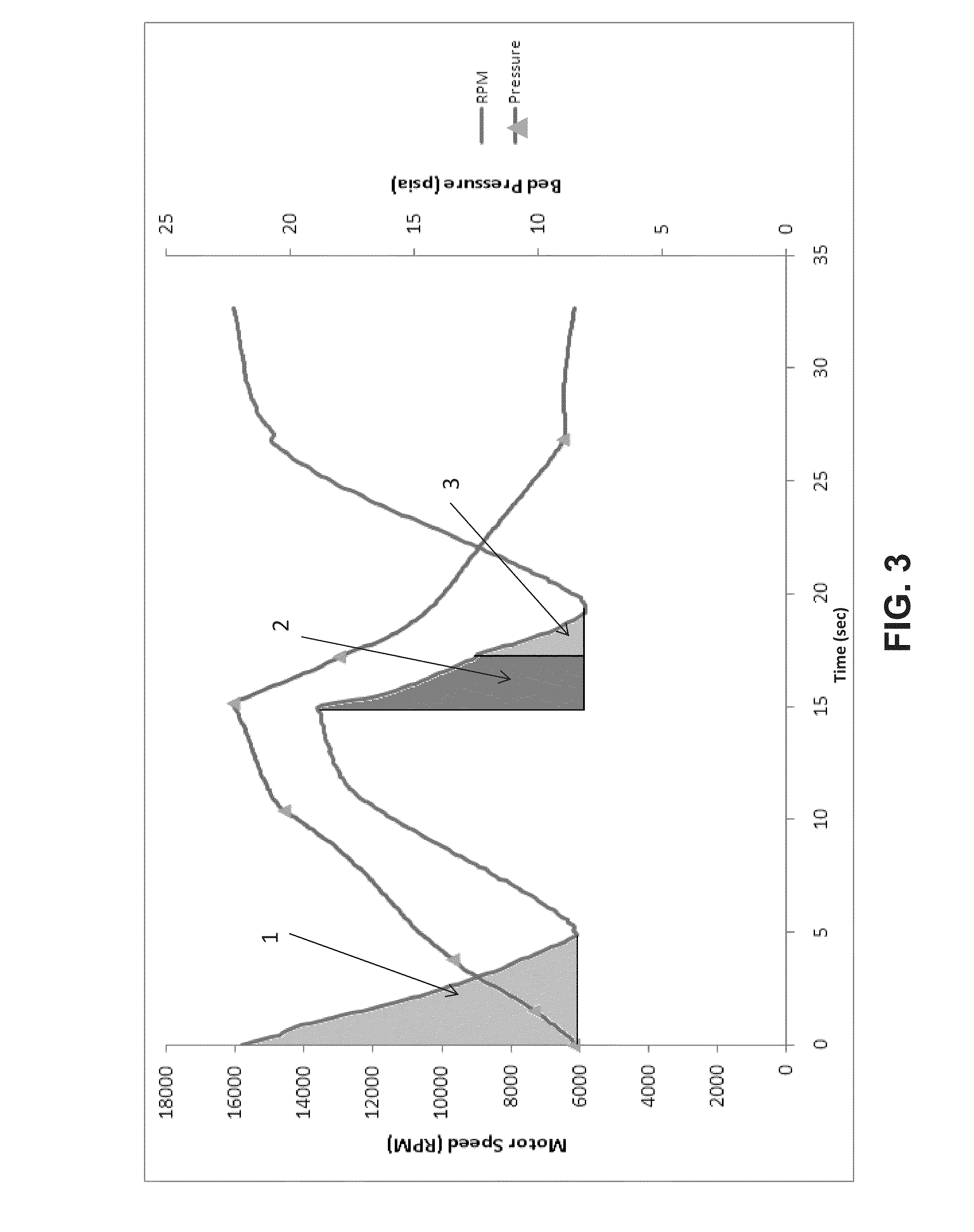
Although centrifugal machines are known to be more efficient than conventional positive displacement machines, the power advantages are not realized when used in such cyclic processes operating under acceleration and deceleration conditions unless the process cycle time is adjusted to be more than a predetermined value calculated based on the moment of inertia of the centrifugal impeller and other moving parts.

Method used


Image

  • Cyclic adsorption process using centrifugal compressors
  • Cyclic adsorption process using centrifugal compressors
  • Cyclic adsorption process using centrifugal compressors

Examples


Embodiment Construction

[0026]As described above, the present invention provides an improved system and process for the use centrifugal compressors in cyclic adsorption processes. This system and process uses centrifugal compressors driven by variable, high speed motors to replace conventional positive displacement machines and more specifically rotary lobe blowers / compressors to minimize power consumption and maximize process efficiency. Further, the selection of cycle time minimizes the occurrence of stonewall found to result from the use of such centrifugal compressors in these rapid cyclic adsorption processes.

[0027]This invention is directed to cyclic fluid separation processes and particularly to cyclic adsorption processes having at least one vessel containing at least one adsorbent bed therein (herein an “adsorber bed” or “adsorber vessel”). Examples of commercial systems include, but are not limited to, PSA and VPSA processes and systems wherein an adsorbent bed is used to separate a less absorbab...


PUM

PropertyMeasurementUnit
cycle timeaaaaaaaaaa
process cycle timeaaaaaaaaaa
inertial energyaaaaaaaaaa

Abstract

A cyclic adsorption process is provided, the process containing one or more adsorber vessels undergoing the steps of at least pressurization and depressurization and driven by one or more variable speed centrifugal machines operating under acceleration and deceleration conditions and adjusted to the steps, vessel size, and process conditions employed, wherein the process cycle time is greater than the ratio of the change in inertia, defined the maximum energy that can be lost during a cycle due to inertia changes, to 0.3 times the total power of the one of more centrifugal machines that would be consumed in the absence of inertial effects.

Description

RELATED APPLICATIONS[0001]This application claims the benefit of U.S. application Ser. No. 13 / 168,264, filed on Jun. 24, 2011, which is incorporated herein by reference.FIELD OF THE INVENTION[0002]The present invention provides an improved cyclic adsorption system and process for separating components of a gas stream using centrifugal machines. More particularly, the present invention is directed to adsorption processes using one or more variable speed driven centrifugal compressors operating under cyclic acceleration and deceleration conditions wherein the process cycle time is selected to minimize the compressor power consumption and maximize the efficiency of the process.BACKGROUND OF THE INVENTION[0003]Cyclic adsorption processes are well know and are typically used to separate a more absorbable component gas from a less absorbable component gas. Examples include pressure swing adsorption (PSA) or vacuum pressure swing adsorption (VPSA) processes which use a low pressure or a va...

Claims


Application Information

Patent Timeline
Patent Type & Authority Applications(United States)
IPC IPC(8): B01D53/047
CPCB01D53/0476B01D2256/12B01D53/047B01L9/54F04D27/0261Y02B30/70B01D53/02F01D17/00
Inventor BELANGER, PAUL W.MANNING, MICHAEL S.ROSINSKI, ANDREW C.
Owner PRAXAIR TECH INC
Learn More