Inspecting apparatus, robot apparatus, inspecting method, and inspecting program
a robot apparatus and inspection method technology, applied in the direction of image analysis, image enhancement, instruments, etc., can solve the problems of difficult to detect a defect of the inspection target object, difficult to set an exposure time for obtaining a combined image suitable for inspection, etc., and achieve the effect of high determination accuracy
- Summary
- Abstract
- Description
- Claims
- Application Information
AI Technical Summary
Benefits of technology
Problems solved by technology
Method used
Image
Examples
first embodiment
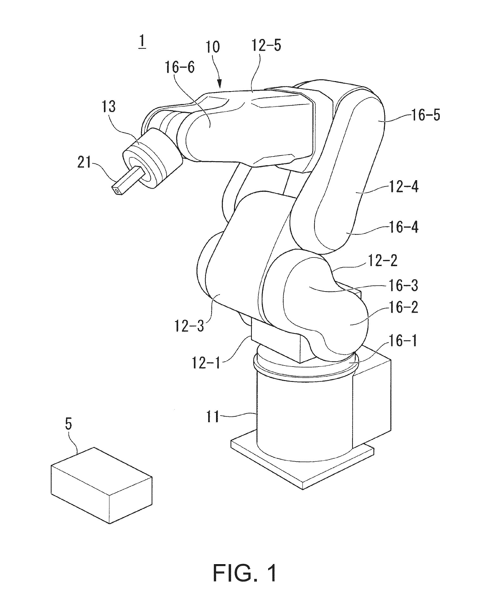
[0037]FIG. 1 is a schematic external view of a robot main body in a robot apparatus according to a first embodiment of the invention and an inspection target object. As shown in the figure, a robot apparatus 1 includes a robot main body 10 provided with an image pickup unit 21.
[0038]The robot apparatus 1 includes link sections 12-1 to 12-5, joint sections 16-1 to 16-6, and a link section 13. The link section 12-1 is coupled to a supporting table 11 via the joint section 16-1. The link section 12-2 is coupled to the link section 12-1 via the joint section 16-2. The link section 12-3 is coupled to the link section 12-2 via the joint section 16-3. The link section 12-4 is coupled to the link section 12-3 via the joint section 16-4. The link section 12-5 is coupled to the link section 12-4 via the joint section 16-5. That is, the link section 12-5 is coupled to the supporting table 11 via the link sections 12-1 to 12-4 and the joint sections 16-1 to 16-5 to be capable of turning and cap...
second embodiment
[0094]The inspecting apparatus 20 included in the robot apparatus 1 according to the first embodiment has the configuration in which the weighted-image-data generating unit 222 generates weighted image data using the Laplacian filter. The inspecting apparatus 20 included in the robot apparatus 1 according to a second embodiment of the invention has a configuration in which a weighted-image-data generating unit 222a generates weighted image data using a Gaussian filter. The Gaussian filter extracts pixels having luminance values in a predetermined range among pixels included in input image data and outputs image data formed by the extracted pixels.
[0095]The inspecting apparatus 20 according to this embodiment is explained below with reference to FIGS. 9 and 10. In this embodiment, components same as the components in the first embodiment are denoted by the same reference numerals and signs and explanation of the components is omitted.
[0096]FIG. 9 is a block diagram showing a function...
third embodiment
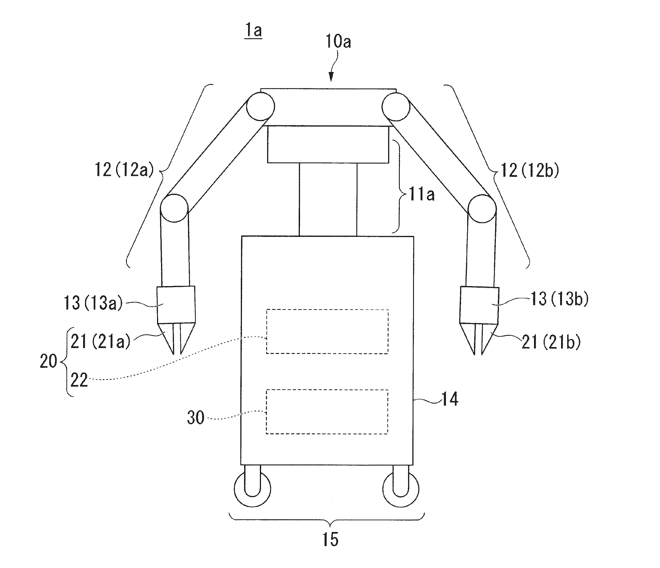
[0109]The robot apparatus 1 according to the first embodiment and the second embodiment has the configuration in which the supporting table 11 is fixed and set on the floor. A robot apparatus 1a according to a third embodiment of the invention has a configuration in which a pedestal section 14 supports a supporting table 11a and includes a portable section 15.
[0110]The robot apparatus 1a according to this embodiment is explained below with reference to FIG. 11. In this embodiment, components same as the components in the first and second embodiments are denoted by the same reference numerals and signs and explanation of the components is omitted.
[0111]FIG. 11 is a schematic external view of the robot apparatus 1a according to the third embodiment of the invention.
[0112]As shown in the figure, the robot apparatus 1a includes a robot main body 10a, the pedestal section 14, and the portable section 15.
[0113]The robot main body 10a includes the supporting table 11a, a first link section...
PUM
 Abstract
Description
Claims
Application Information
 - R&D
- Intellectual Property
- Life Sciences
- Materials
- Tech Scout
- Unparalleled Data Quality
- Higher Quality Content
- 60% Fewer Hallucinations
Browse by: Latest US Patents, China's latest patents, Technical Efficacy Thesaurus, Application Domain, Technology Topic, Popular Technical Reports.
© 2025 PatSnap. All rights reserved.Legal|Privacy policy|Modern Slavery Act Transparency Statement|Sitemap|About US| Contact US: help@patsnap.com


