
Organic light emitting diode display having photodiodes

a light-emitting diode and organic technology, applied in the field of electromechanical displays, can solve the problems of poor display quality of unevenly aged displays, prolong the useful life of displays, and reduce the quality of displayed images, so as to improve the versatility of displays and improve the appearance of displays. , the effect of improving the versatility of displays

Active Publication Date: 2013-08-01
APPLE INC
View PDF6 Cites 77 Cited by
  • Summary
  • Abstract
  • Description
  • Claims
  • Application Information

AI Technical Summary

Benefits of technology

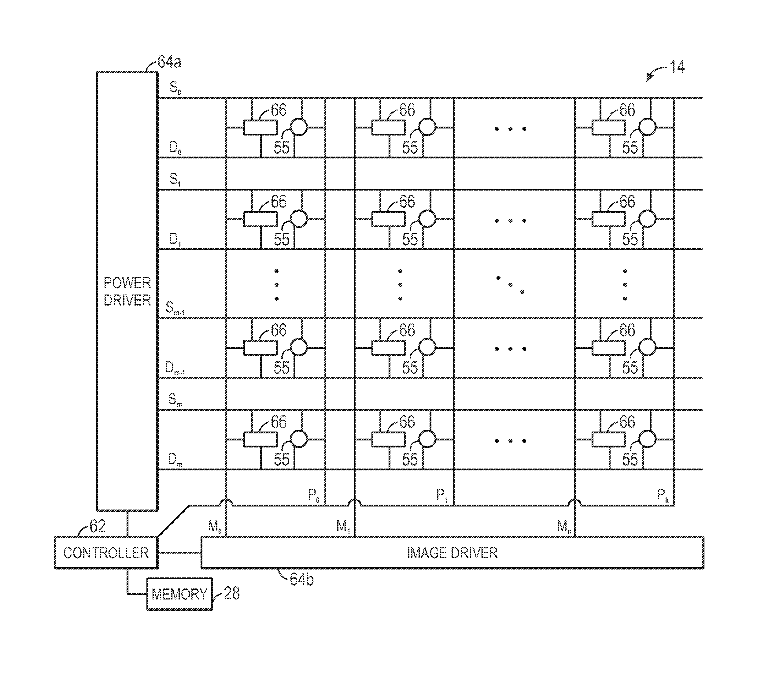
The present invention is related to adjusting OLED displays to maintain a desirable appearance. The invention involves using photodetectors to detect light incident to the display, which can affect how the light emitted from the display is perceived. By analyzing the detected light, controllers can brighten or dim the entire display and / or compensate each OLED or group of OLEDs to improve the appearance of the display as a whole. This improves the versatility of the display in different operating environments. Additionally, the invention also allows for compensating individual OLEDs for shifts in brightness and / or color based on the photodetector measurements of each OLED's aging. This adjusted OLED may now emit light at a desired brightness and / or color. This prolongs the useful life of a display and maintains a desirable display appearance for longer than would otherwise be possible.

Problems solved by technology

Aged OLEDs may emit light different from less aged OLEDs, which may result in a poor display quality for unevenly aged displays.
As portions of the display age at different rates, the quality of a displayed image may decrease.
This may prolong the useful life of a display and maintain a desirable display appearance for longer than would otherwise be possible.

Method used


Image

  • Organic light emitting diode display having photodiodes
  • Organic light emitting diode display having photodiodes
  • Organic light emitting diode display having photodiodes

Examples


Embodiment Construction

[0027]One or more specific embodiments will be described below. In an effort to provide a concise description of these embodiments, not all features of an actual implementation are described in the specification. It should be appreciated that in the development of any such actual implementation, as in any engineering or design project, numerous implementation-specific decisions must be made to achieve the developers' specific goals, such as compliance with system-related and business-related constraints, which may vary from one implementation to another. Moreover, it should be appreciated that such a development effort might be complex and time consuming, but would nevertheless be a routine undertaking of design, fabrication, and manufacture for those of ordinary skill having the benefit of this disclosure.

[0028]When introducing elements of various embodiments of the present disclosure, the articles “a,”“an,” and “the” are intended to mean that there are one or more of the elements....


PUM


Abstract

Systems, methods, and devices are provided in which photodetectors disposed throughout a display are used to control the display brightness. The photodetectors are to be used for ambient light sensing, proximity sensing, or to compensate for aging OLEDs. In some embodiments, photodiodes are fabricated with OLEDs during the TFT fabrication process. In some embodiments, the photodetectors may be disposed throughout the display in zones containing OLEDs. The photodetectors are used to control the display brightness and color for the OLEDs in areas around each photodetector based on ambient light, aging, and / or nearby objects. A controller makes driving strength adjustments to the OLEDs in each zone independent of other zones. Photodetectors disposed throughout the display may improve proximity sensing and provide additional functionality to the device.

Description

BACKGROUND[0001]The present disclosure relates generally to electronic displays and, more particularly, to photodetectors in a display.[0002]This section is intended to introduce the reader to various aspects of art that may be related to various aspects of the present disclosure, which are described and / or claimed below. This discussion is believed to be helpful in providing the reader with background information to facilitate a better understanding of the various aspects of the present disclosure. Accordingly, it should be understood that these statements are to be read in this light, and not as admissions of prior art.[0003]Electronic devices and systems increasingly include display screens as part of the user interface of the device or system. As may be appreciated, display screens may be employed in a wide array of devices and systems, including desktop computer systems, notebook computers, and handheld computing devices, as well as various consumer products, such as cellular p...

Claims


Application Information

Patent Timeline
Patent Type & Authority Applications(United States)
IPC IPC(8): G06F3/041G09G5/10H01J9/00
CPCG06F3/0412G06F3/0421G09G3/3208G09G2320/0233G09G2360/147G09G2320/029G09G2320/045G09G2360/144G09G2320/0242G09G2320/043G09G2320/0626G09G2320/0666
Inventor LYNCH, STEPHEN BRIANDRZAIC, PAUL STEPHENRAPPOPORT, BENJAMIN MARKROTHKOPF, FLETCHER R.TERNUS, JOHN PATRICKMYERS, SCOTT ANDREW
Owner APPLE INC
Learn More