
Excavation system

Active Publication Date: 2013-07-25
BOH BROS CONSTR CO
View PDF19 Cites 20 Cited by
  • Summary
  • Abstract
  • Description
  • Claims
  • Application Information

AI Technical Summary

Benefits of technology

This patent describes an excavation system that has the following technical benefits: increased mobility and maneuverability, simple operation without special training, and the ability to provide extensive trenching with minimal downtime. These features reduce the risk of environmental and safety hazards for operating personnel and ultimately save time and money.

Problems solved by technology

However, these prior art devices are not capable of operating in all of the various field conditions where the excavation may be desired.
In many instances these excavators do not have the mobility necessary to efficiently make the desired shaped trench, or the ability to maneuver in narrow spaces to get to the excavation site, or require too much down time to dispose of the collected excavated soil or are not constructed to efficiently excavate the site.
Nor are this prior art devices constructed to deliver other equipment or material to the excavated site without extensive maneuvering or removal of field structures.
Yet another problem is the requirement for extensive equipment operator training.
Still further, many of these prior art excavators required multiple personnel to operate the excavation equipment.
In many cases the operating personnel have to be positioned in environmental or safety hazardous places that can cause harm or injury to the operating personnel.
Still further, many of these prior art excavators do not have the ability to perform other function that are commonly required in a trenching operation, such as breaking up concrete, picking up and removing obstacles to the excavation process, or cutting material for removal from the excavation site, etc. thus requiring additional equipment and lost down time.
In addition, it is difficult to determine the depth of the excavation during the excavating process, as well as it is difficult for the operator of the excavation equipment to confirm that soil is actually being excavated or determine if the excavated material may be clogging the vacuum hose that removes the material from the site.
Another problem with the use of these prior art excavation devices is damage caused by the trenching tubes striking the coated surfaces of pipes and / or utility lines that are buried underground at the excavation site.
Also, a problem is the inability of these prior art excavation devices to be able to detect if explosive gases or environmentally harmful fumes have been released during the excavation operations.
Finally, these prior art excavators are primarily constructed to perform vertical surface trenching, and are not capable of efficiently performing horizontal trenching under pipes or other surface material, such as a concrete slab.

Method used


Image

  • Excavation system
  • Excavation system
  • Excavation system

Examples


Embodiment Construction

[0050]Without any intent to limit the scope of this invention, the preferred embodiments of the invention are described for an embodiment specifically adopted for use in industrial plant sites.

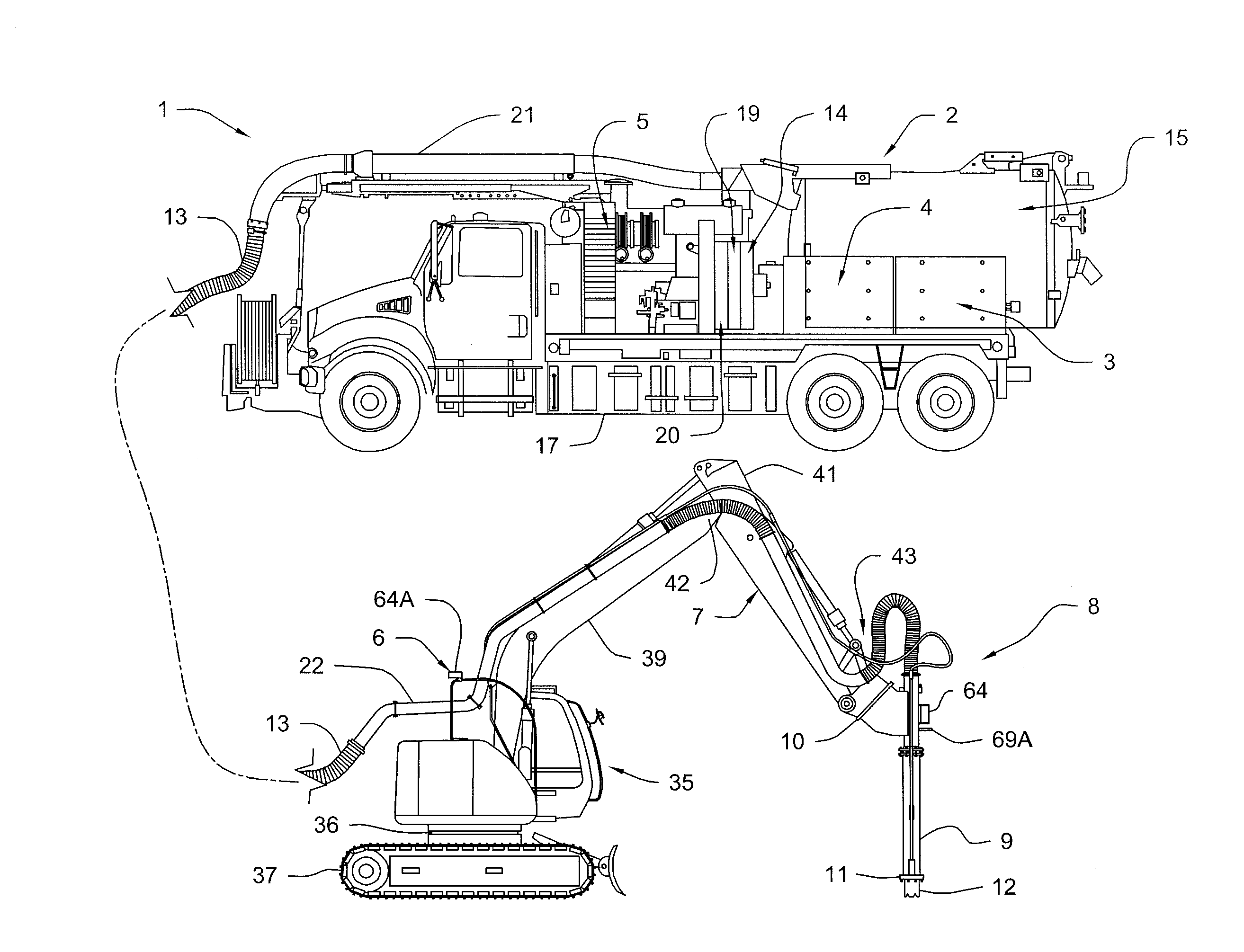
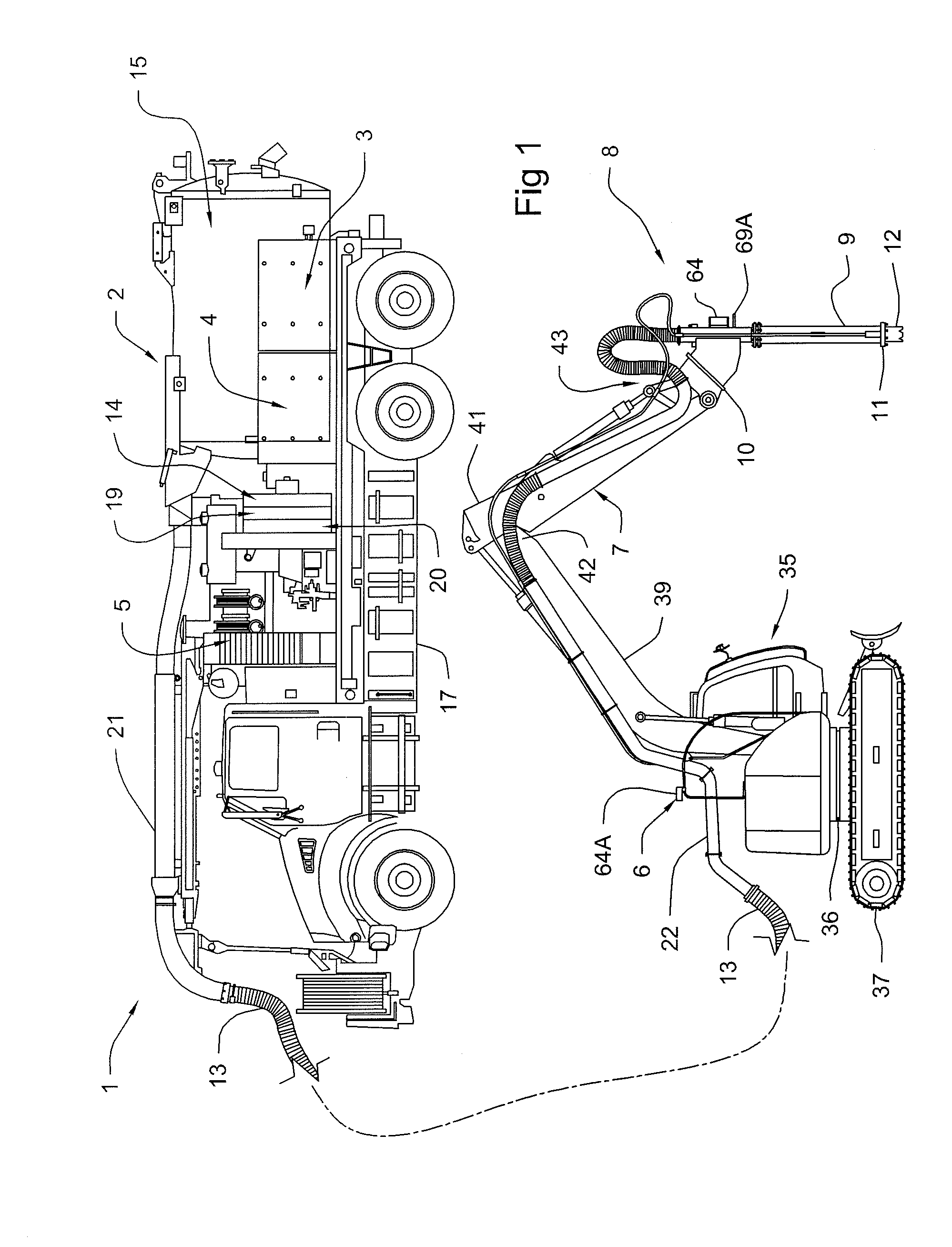
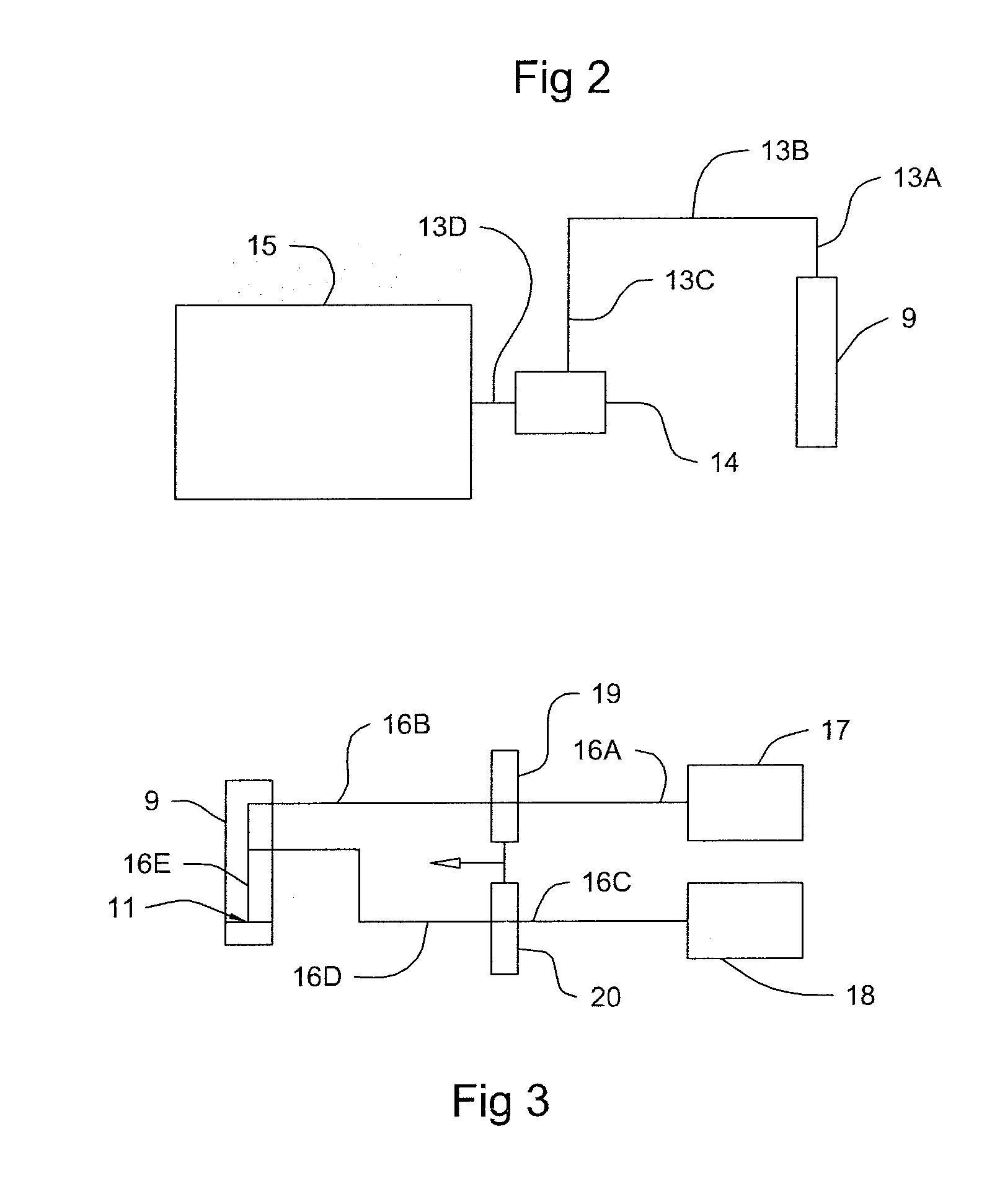
[0051]As indicated in FIG. 1 in one preferred embodiment of the invention the excavation system 1 comprises a first vehicle, such as a conventional vacuum truck 2, having mounted thereon a vacuum assembly 3, a high pressure fluid delivery assembly 4, one or more power sources 5 used to operate the vacuum assembly 3 and the high pressure fluid delivery assembly 4. The excavation system 1 also comprises a relatively small, maneuverable vehicle 6 having an extendible and articulating arm 7, such as a small backhoe. The excavation system 1 still further comprises an excavator assembly 8 having a rigid excavator tube 9 attachable to the extendible and articulating arm 7 of the backhoe 6 via a mounting adaptor 10. The excavator assembly 8 also includes a fluid jetting assembly 11 having nozzles 12 d...


PUM


Abstract

An excavation system utilizes a vacuum truck having a vacuum system in combination with a small backhoe to which an excavator assembly is affixed to the backhoe extendable and articulating arm whereby manipulation of the excavator assembly can be controlled by an operator positioned in the backhoe operator cab. The vacuum assembly and the excavator assembly are operatively attached by an elongated, at least partially flexible vacuum hose operatively attached to the vacuum truck pump to permit material that is excavated to be transported from the excavator assembly to the vacuum assembly for storage or disposal.

Description

BACKGROUND OF THE INVENTION[0001]1. Field of the Invention[0002]This invention relates in general to excavators, and more particularly to soil excavators used for trenching at commercial and industrial sites.[0003]2. Background of the Invention[0004]There has been for some time various water jet / vacuum excavators used to expose underground utilities or piping, as well as for cutting precise trenches for installation of utility lines or piping.[0005]In these prior art excavators, the excavation is achieved through use of a high pressure water jet (>1,200 psi) and the removal of the excavated soil through use of a vacuum system. One example of such excavators is described in U.S. Pat. No. 6,484,422. However, these prior art devices are not capable of operating in all of the various field conditions where the excavation may be desired. In many instances these excavators do not have the mobility necessary to efficiently make the desired shaped trench, or the ability to maneuver in na...

Claims


Application Information

Patent Timeline
IPC IPC(8): E02F7/00
CPCE02F7/00B65G53/30Y10S37/905E21B7/18E02F3/925E02F3/90E02F3/8825E02F3/905
Inventor LAMONTE, LARRY R.
Owner BOH BROS CONSTR CO
Learn More