
Method and Apparatus for Magnetic Response Imaging

a magnetic response and imaging technology, applied in the direction of magnetic property measurement, material magnetic variables, instruments, etc., can solve the problems of inability to continuously monitor the pipeline, difficult to detect small changes in conductivity of metals, etc., to achieve the effect of convenient detection and measurement of metal corrosion losses, effective and economical

Inactive Publication Date: 2013-07-25
SINGER JEROME R
View PDF0 Cites 22 Cited by
  • Summary
  • Abstract
  • Description
  • Claims
  • Application Information

AI Technical Summary

Benefits of technology

The patent describes a system that can detect, measure, and monitor the status of iron and steel pipes and pipelines to prevent corrosion and deterioration. It can work on insulated and un-insulated pipes, both underground and in sea water. The system is sensitive to corrosion and can easily detect and measure metal corrosion losses as low as one tenth of one percent of metal loss.

Problems solved by technology

In practice, it is difficult to detect the small changes in conductivity of a metal as it corrodes, since the effects of the corrosion will generally be very small compared to the remaining metal.
It is not practicable for continuous monitoring of a pipeline for corrosion because the system stability of the transmission line is not sensitive to small levels of corrosion.

Method used


Image

  • Method and Apparatus for Magnetic Response Imaging
  • Method and Apparatus for Magnetic Response Imaging
  • Method and Apparatus for Magnetic Response Imaging

Examples


Embodiment Construction

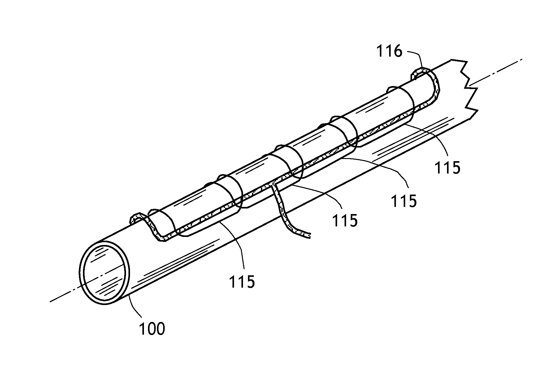
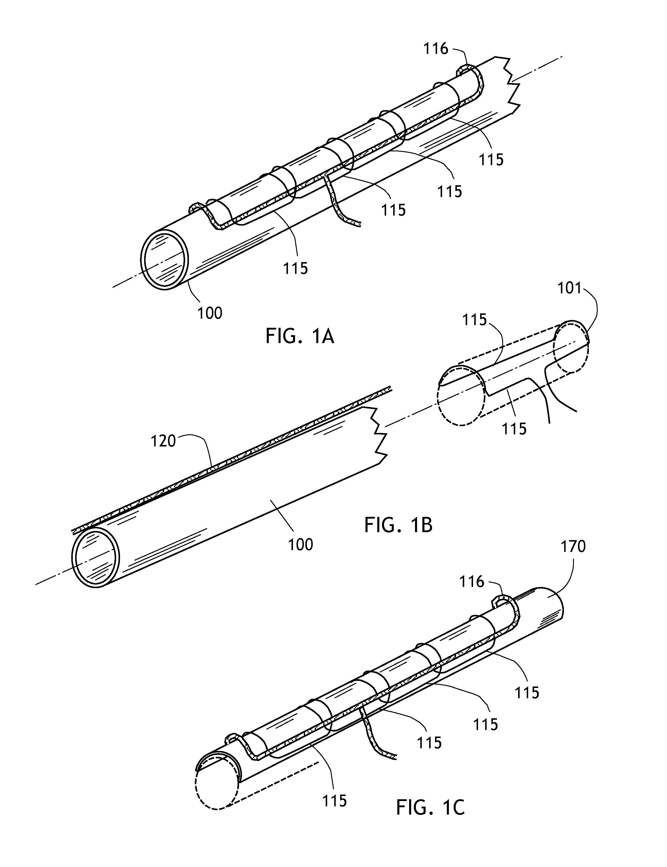
[0027]FIG. 1A schematically shows part of one of the configurations of our advanced Magnetic Response Imaging (MRI), system. A pipeline section 100 has receiving coils 115 which are saddle coils in this configuration. The saddle coils 115 are generally multiple turn coils, though they are illustrated as single turn coils for ease of illustration. These coils are placed on the pipeline with the longitudinal axis parallel to the axis of pipeline 100. Several receiving coils are shown along the pipeline. They are showing overlapping, or they can also be placed consecutively end-to-end along the pipeline. Each receiving coil can be interrogated periodically by remote switching to each coil consecutively or in some designated order. Each receiving coil provides a voltage value which is determined by the status of the metal under each coil in the pipeline. FIG. 1B shows one form of the receiving coils more clearly. Again, only one turn is shown to provide clarity though multiple turns are...


PUM

PropertyMeasurementUnit
corrosionaaaaaaaaaa
magnetic domainsaaaaaaaaaa
magneticaaaaaaaaaa

Abstract

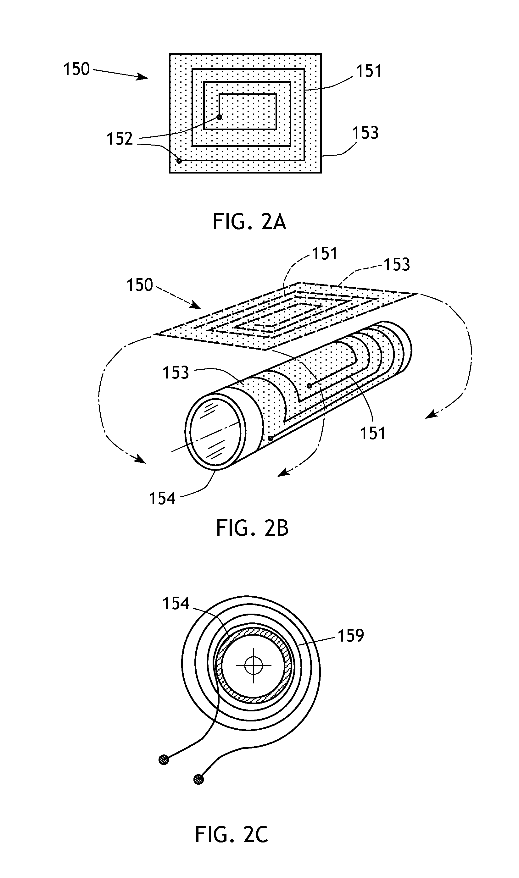
A method for identifying, measuring, and monitoring metal loss through corrosion ferromagnetic piping includes drive coils secured to the pipe and driven to emit a magnetic field which is transmitted through the object by magnetic domains in the object. Response coils detect the magnetic domains and generate a response signal. Response coils may be saddle or loop coils, or printed coils on flexible substrates that are applied to conform to the pipe peripheral surface. The system operates reiteratively over an extended period of time to detect loss of magnetic domains which is an important indicator of corrosion and deterioration of the object.

Description

CROSS-REFERENCE TO RELATED APPLICATIONS[0001]This application is a continuation-in-part of application Ser. No. 12 / 927,756, filed Nov. 22, 2010, for which priority is claimed.FEDERALLY SPONSORED RESEARCH[0002]Not applicable.SEQUENCE LISTING, ETC ON CD[0003]Not applicable.BACKGROUND OF THE INVENTION[0004]1. Field of the Invention[0005]The present invention relates to apparatus and methods which can be utilized for identifying, measuring, and monitoring metal loss through corrosion or other deleterious factors in ferromagnetic piping and ferromagnetic vessels.[0006]2. Description of Related Art[0007]The following patents and publications exemplify the state of the art in systems for detecting corrosion in metallic systems, particularly pipes and pipelines.[0008]Patent Publication No. US2002 / 0153249 by Eric Atherton describes a metallic corrosion monitoring system which employs the measurement of electrical current flow in the metal. This method is not as sensitive as the present inven...

Claims


Application Information

Patent Timeline
Patent Type & Authority Applications(United States)
IPC IPC(8): G01N27/82
CPCG01N27/82G01N17/006G01N27/87G01R33/1223
Inventor SINGER, JEROME R.
Owner SINGER JEROME R
Learn More