Conduit structure for molten glass, vacuum degassing apparatus, vacuum degassing method for molten glass and process for producing glass products employing said conduit structure

a conduit structure and glass technology, applied in the direction of mechanical equipment, glass rolling equipment, manufacturing tools, etc., can solve the problems of inability to obtain sufficient removal effect, adverse effects of components on glass production, and inability to achieve sufficient removal effect, etc., to suppress excessive stress, prevent excessive concentration of stress, and increase rigidity

Active Publication Date: 2013-07-25
ASAHI GLASS CO LTD
View PDF0 Cites 9 Cited by
  • Summary
  • Abstract
  • Description
  • Claims
  • Application Information

AI Technical Summary

Benefits of technology

[0039]In a conduit structure having a double pipe structure comprising an inner pipe and an outer pipe, a supporting rib connecting the inner pipe and the outer pipe employs a structure having an inner straight portion to be joined with the inner pipe, an outer straight portion to be joined with the outer pipe and a connecting wall portion, and a concave portion extending along each side end of the connecting wall portion and reaching end portions of the inner straight portion and the outer straight portion, is formed. Consequently, it is possible to prevent excessive concentration of stress in any of an inner pipe-joined portion, an outer pipe-joined portion and the supporting rib. Further, since a projecting portion is provided at each of both ends of each of the inner straight portion and the outer straight portion, the projecting portion of the supporting rib can deform so as to follow deformation of the outer pipe or the inner pipe, and it is possible to realize a conduit structure wherein excessive stress concentration in the inner pipe-joined portion, the outer pipe-joined portion of the supporting rib as well as the supporting rib itself, hardly occurs.
[0040]In the supporting rib, when the concave portion is formed to continue to the inner straight portion or the outer straight portion via a rounded portion continuing from the inside of the concave portion, and a rectangular projection having a uniform thickness is provided on further outside of each straight portion, each projecting portion of the supporting rib can flexibly deform so as to follow deformation of the outer pipe or the lower pipe, and it is possible to realize a conduit structure wherein excessive concentration of stress on the inner pipe-joined portion and the outer pipe-joined portion hardly occurs.
[0041]In the supporting rib, when the leading edge portion of the rectangular projection has a shape that forms a step portion with respect to the outer face of the inner pipe or the inner face of the outer pipe, it is possible to eliminate a sharp portion at the leading edge of the rectangular projection. Accordingly, after joining by e.g. welding, when a stress is applied to the supporting rib by weight of the inner pipe and the supporting rib is forced to deform in the rotational direction, no stress is applied in such a way that the leading edge of the rectangular projection breaks the inner pipe or the outer pipe. Accordingly, even with a structure of a supporting rib provided with the rectangular projection, there is no risk of breaking the inner pipe or the outer pipe.
[0042]When the depth of the concave portion formed in the supporting rib is within a range of from 10 to 42% based on the total length of the inner straight portion and the outer straight portion, whichever longer, each rectangular projection in each projecting portion formed on each side of the inner straight portion or the outer straight portion is easily deformed to follow deformation of the inner pipe or the outer pipe, whereby it is possible to realize a conduit structure wherein excessive concentration of stress on the inner pipe or the outer pipe hardly occurs.
[0043]When the outer pipe is thicker than the inner pipe and the outer straight portion is longer than the inner straight portion, since the rotational displacement of the supporting rib is dominated by the outer pipe having higher rigidity, when the projecting portion having high deformation-following property is formed on each end of the outer straight portion of the supporting rib, it is possible to suppress excessive concentration of stress on the joined portion between the outer pipe and the supporting rib. This structure contributes to significant reduction of stress formed in a joined portion between the supporting rib and the outer pipe.
[0044]When a vacuum degassing apparatus or a vacuum degassing method employs the above conduit structure, it is possible to obtain an effect of eliminating excessive concentration of stress in a portion of the conduit structure in the vicinity of the supporting rib, and achieving a long term safe operation.

Problems solved by technology

However, when such a melted component is uniformly dispersed in the molten glass, it is considered to be unlikely that such a component adversely affect a glass to be produced.
When such foreign objects remain inside the molten glass, glass produced from the molten glass may have defects.
Here, when the conduit is made of a metal other than platinum or a platinum alloy, the same problem occurs.
In the conduit structure for molten glass, as a conventional structure for removing foreign objects or bubbles mixed in the molten glass, a drain out structure, an overflow structure, etc. have been employed, but there has been a problem that sufficient removal effect cannot be easily obtained.

Method used


Image

  • Conduit structure for molten glass, vacuum degassing apparatus, vacuum degassing method for molten glass and process for producing glass products employing said conduit structure
  • Conduit structure for molten glass, vacuum degassing apparatus, vacuum degassing method for molten glass and process for producing glass products employing said conduit structure
  • Conduit structure for molten glass, vacuum degassing apparatus, vacuum degassing method for molten glass and process for producing glass products employing said conduit structure

Examples


Embodiment Construction

[0059]Now, an embodiment of a conduit structure for molten glass according to the present invention and a vacuum degassing apparatus provided with such a conduit structure, will be described, but the present invention is not limited to the following embodiments. Further, the conduit structure of the present invention is not limited to a form wherein the axis of the pipe is in vertical direction.

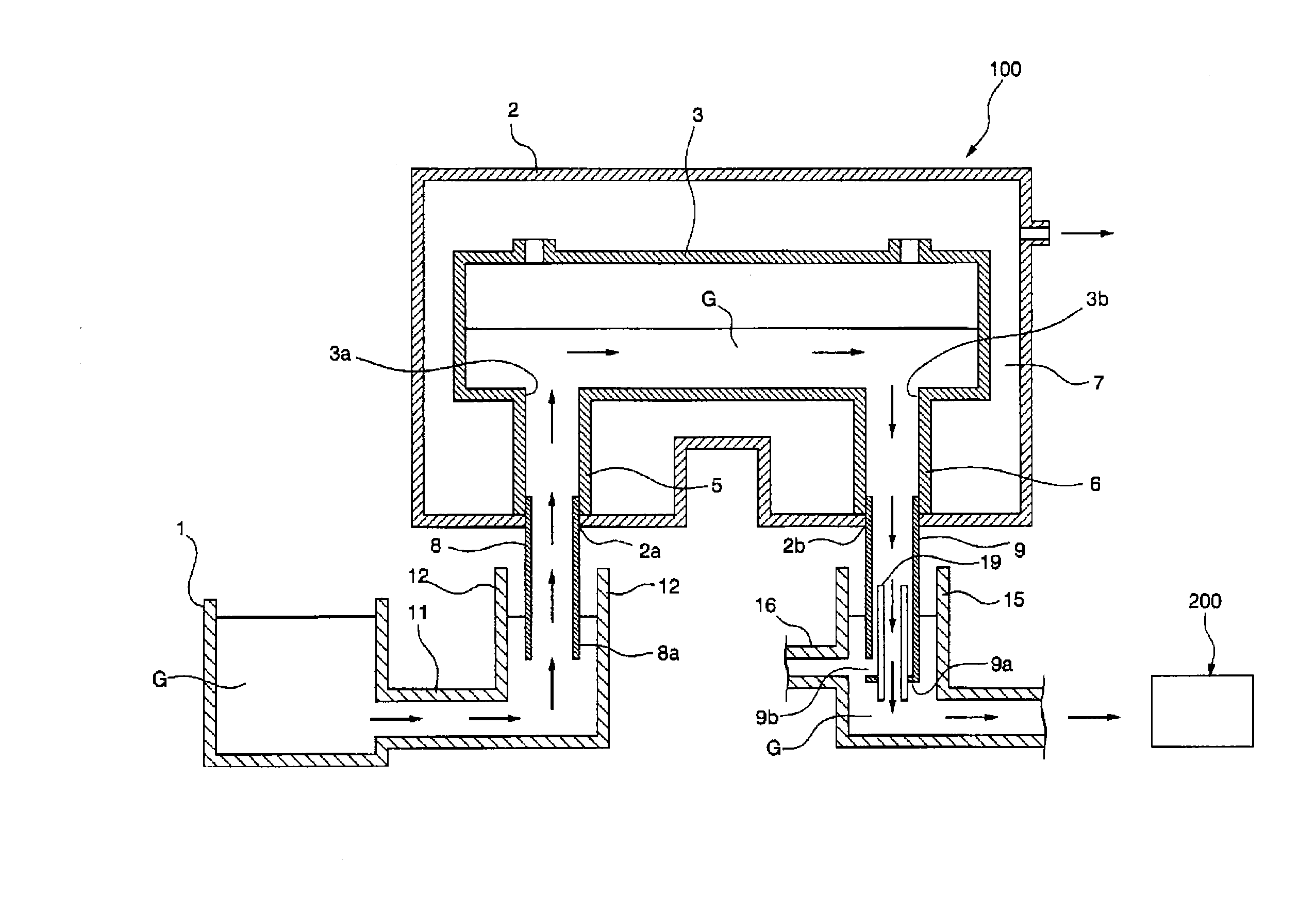
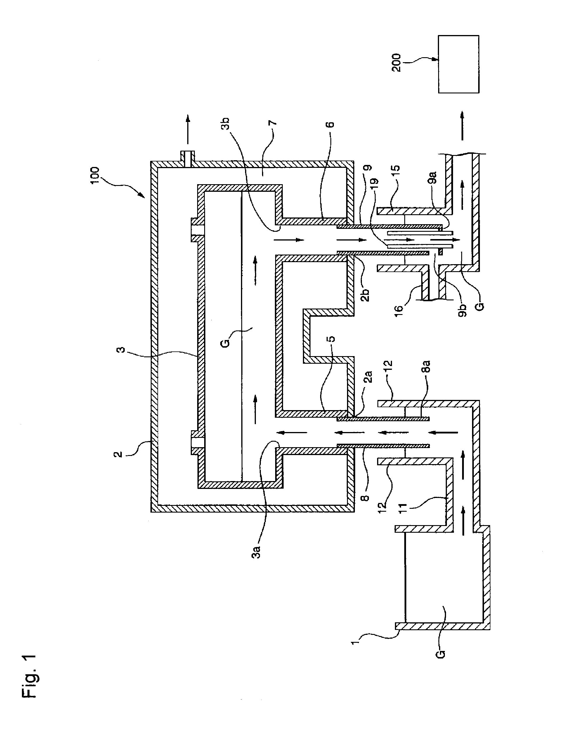
[0060]FIG. 1 is a cross sectional view schematically showing an example of the structure of a vacuum degassing apparatus provided with a conduit structure for molten glass according to the present invention. A vacuum degassing apparatus 100 shown in FIG. 1 is an apparatus to be employed for a process comprising vacuum-degassing molten glass G supplied from a melting tank 1 and continuously supplying the molten glass to a forming apparatus 200 for a subsequent step.

[0061]The vacuum degassing apparatus 100 of this embodiment has a vacuum housing 2 made of a metal such as a stainless steel, insi...


PUM

PropertyMeasurementUnit
widthaaaaaaaaaa
widthaaaaaaaaaa
widthaaaaaaaaaa

Abstract

A conduit structure for molten glass, in which molten glass is flown through a double-pipe structure, with little stress loading even for a long time operation. A supporting rib connecting an inner pipe and an outer pipe is employed in the double pipe structure having the inner pipe and outer pipe in the conduit structure for molten glass, wherein excessive stress concentration hardly occurs in an inner pipe-joint portion, an outer pipe-joint portion and the rib when the rib is applied with a stress load due to the weight of the inner pipe.

Description

TECHNICAL FIELD[0001]The present invention relates to a conduit structure for molten glass, a vacuum degassing apparatus, a vacuum degassing method for molten glass and a process for producing glass products employing such a conduit structure.BACKGROUND ART[0002]A vacuum degassing apparatus has conventionally been employed to remove bubbles generated in molten glass prior to forming of the molten glass in a forming apparatus, the molten glass being produced by melting glass materials in a melting tank, so that the quality of formed glass products can be improved.[0003]The vacuum degassing apparatus comprises a vacuum degassing vessel the interior of which is maintained in a predetermined vacuum level. When the molten glass is passed through the vacuum degassing vessel, bubbles contained in the molten glass grow in a relatively short time. The grown bubbles rise in the molten glass owing to their buoyancy. When they reach the surface of the molten glass, they break themselves whereby...

Claims


Application Information

Patent Timeline
Patent Type & Authority Applications(United States)
IPC IPC(8): C03B5/225
CPCC03B5/2252C03B5/262F16L9/18F16L7/00C03B5/42
Inventor NAGATA, TAKAHIROMIYOSHI, WATARUITOH, HAJIMEHAMAMOTO, HIROAKISASAKI, MICHITO
Owner ASAHI GLASS CO LTD
Why Eureka
Try Eureka