
Mounting system for transmitter receiver modules

a transmitter receiver and module technology, applied in the direction of particular array feeding system, electrical apparatus construction details, association of printed circuit non-printed electric components, etc., can solve the problems of reducing the radar performance of the aesa, and achieve the effect of high packing of trm:s and high maintenance flexibility

Active Publication Date: 2013-07-18
SAAB AB
View PDF5 Cites 19 Cited by
  • Summary
  • Abstract
  • Description
  • Claims
  • Application Information

AI Technical Summary

Benefits of technology

The technical effects of this patent are to overcome the limitations of current technology to allow for a higher packing of TRMs and greater flexibility in maintenance.

Problems solved by technology

Further, as several multipacks are mounted adjacent to each other periodical errors can occur, wherein the radar performance of the AESA decreases.

Method used


Image

  • Mounting system for transmitter receiver modules
  • Mounting system for transmitter receiver modules
  • Mounting system for transmitter receiver modules

Examples


Embodiment Construction

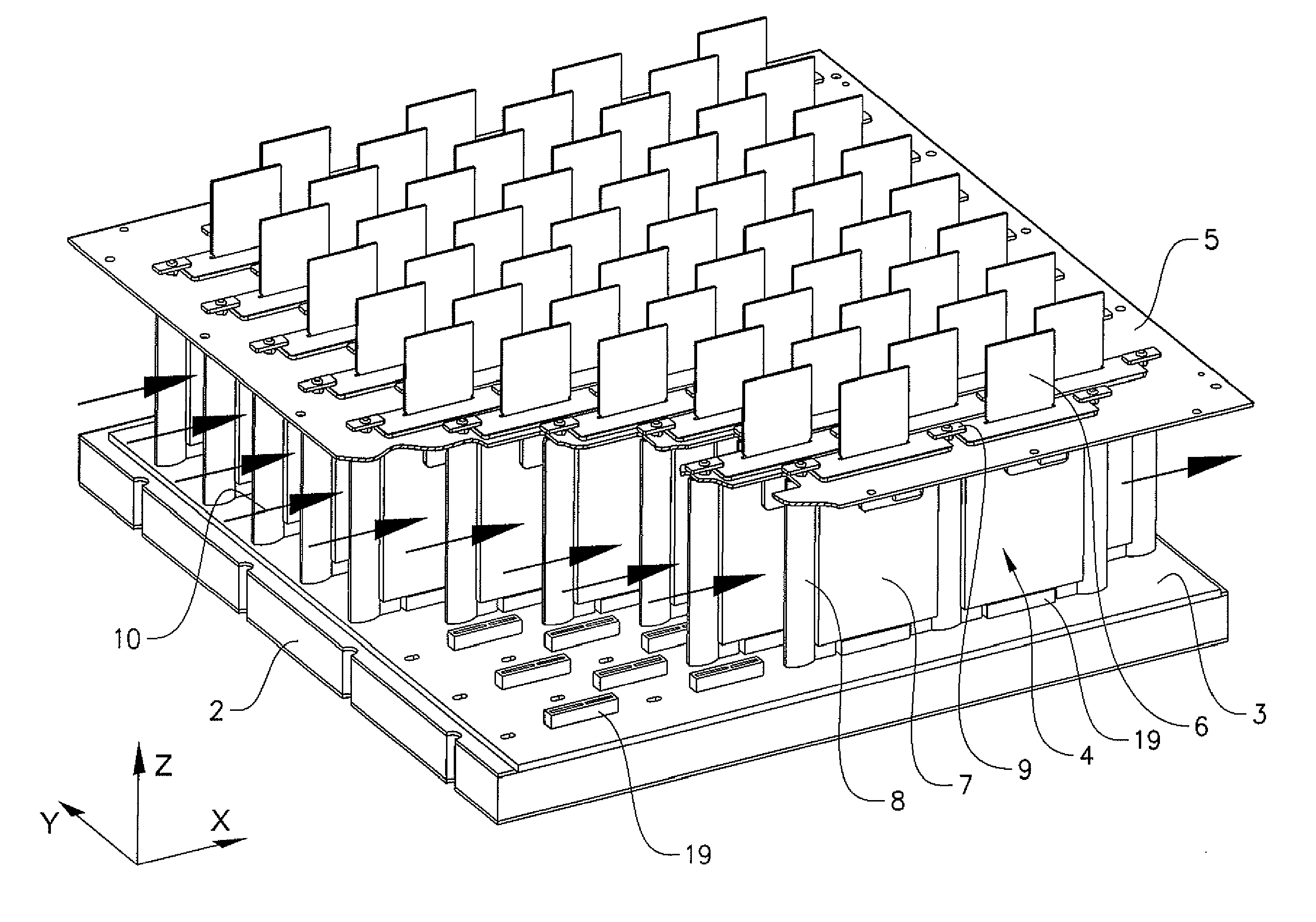
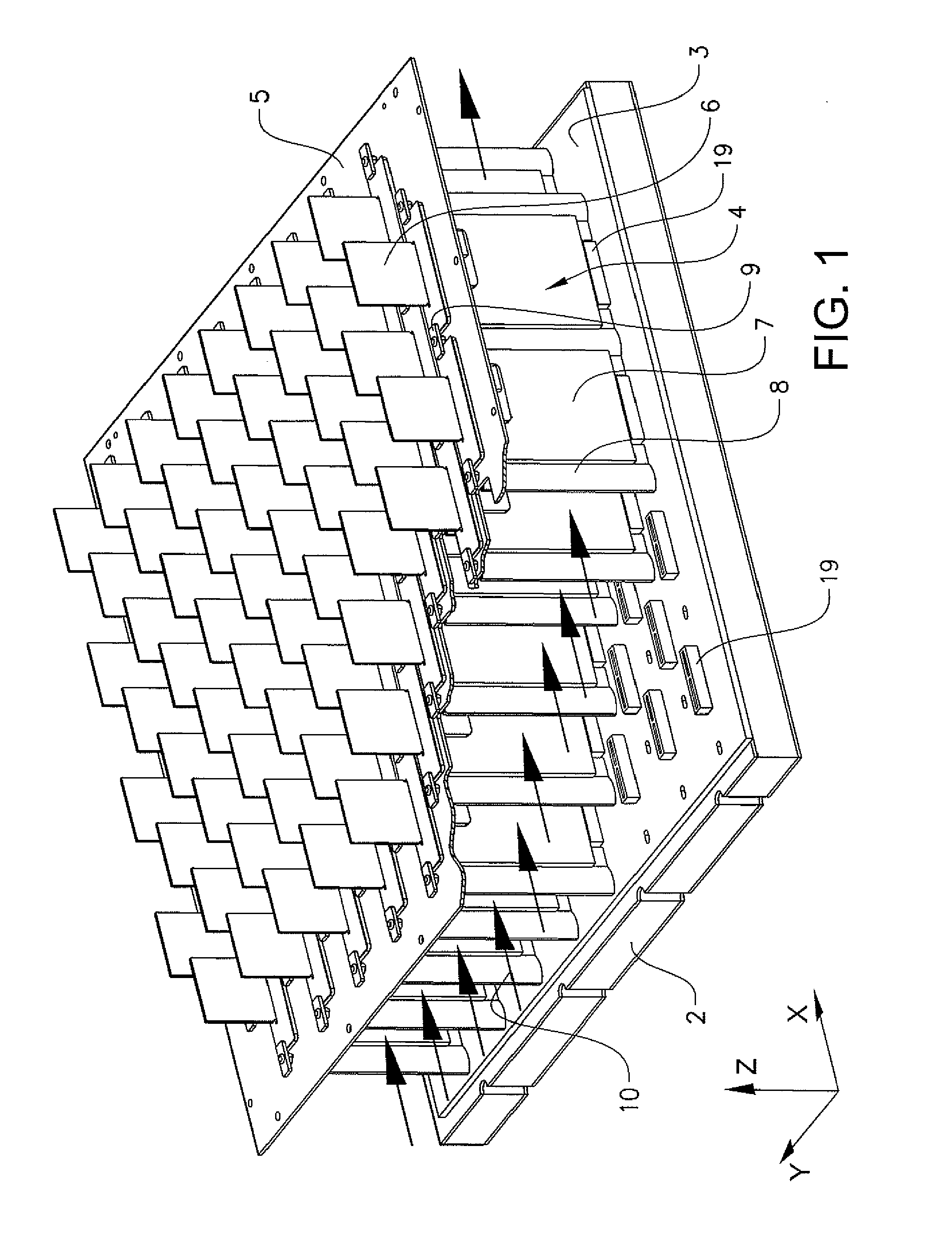
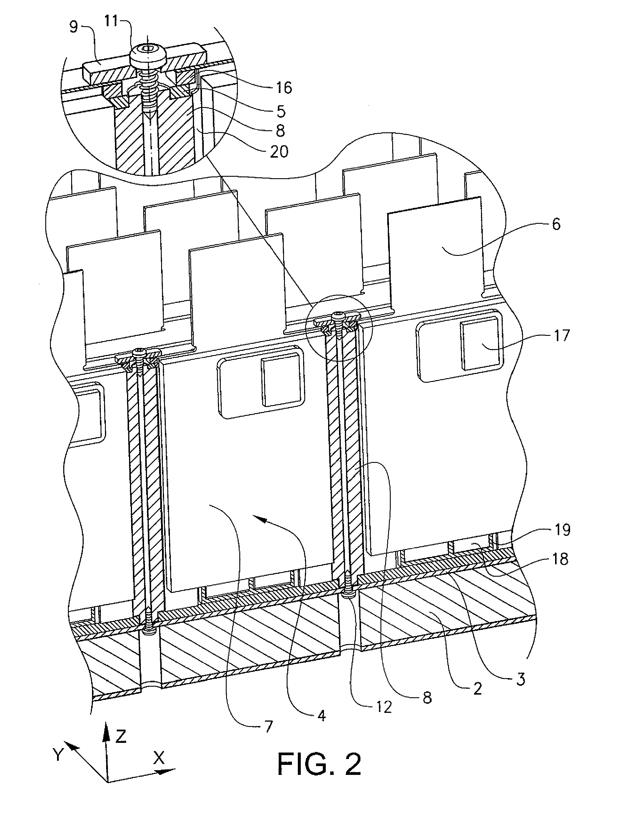
[0032]FIG. 1 illustrates an inventive mounting system in which the TRM:s are mounted in a 8*8 matrix. In the figure is every second row displaced relative its adjacent rows. The mounting system 1 is resting on a sandwich board 2, on which the substrate rear panel 3 is mounted. The substrate rear panel 3 is adapted with TRM contact means, for receiving the TRM:s 4. On the back side of the sandwich board 2 are support units (not shown) mounted. The support units 11 are connected to the substrate rear panel 3 through the sandwich board 2. The support units 11 mounted on the back side of the sandwich board 2 can be exchanged, without having to demount other parts of the mounting system. The substrate rear panel 3 is a passive component of the AESA, i.e. it does not involve any active components and has therefore a low risk of failure. This is an advantage, since, the substrate rear panel 3 is so integrated in the mounting system, that is would be complex and expansive to exchange it.

[00...


PUM


Abstract

A mounting system adapted to receive a plurality of transmitter receiver modules and each including an upper antenna part and a lower electronic components part. The lower part includes transmitter receiver module contacts on the end opposite the upper part. The mounting system includes a substrate rear panel including transmitter receiver module contact receivers on a first side and active support units on a second side. Each contact receiver is adapted to receive transmitter receiver module contacts of one receiver module. The supports are adapted to support a plurality of receiver modules. One single substrate rear panel is adapted to receive the receiver modules in a matrix. The mounting system includes a ground plane and an electric conductive sheet, and is arranged such that when the receiver modules are mounted in the mounting system, the ground plane levels with the receiver modules transition from the upper to the lower part.

Description

TECHNICAL FIELD[0001]The present invention relates to radar and communication systems and more particularly to a mounting system for transmitter receiver modules (TRM:s) in an active electronically scanned antenna (AESA) array. The invention further relates to a TRM for such an inventive mounting system.BACKGROUND ART[0002]AESA arrays are well known. An AESA is based on a high number of TRM:s that can control the direction of the radar beam by adjusting their individual transmission. Today the TRM:s are normally assembled into a multipack of TRM:s, wherein the multipack is mounted together with other multipacks to form the AESA. The TRM:s are mounted in rows in the individual multipacks. The smallest exchange unit is this multipack which must be exchanged in a whole if one of the TRM:s in the multipack is defect. This is obviously a waist of those TRM:s still working in such an multipack. Further, as several multipacks are mounted adjacent to each other periodical errors can occur, ...

Claims


Application Information

Patent Timeline
Patent Type & Authority Applications(United States)
IPC IPC(8): H05K1/18H05K1/02
CPCH01Q1/1207H01Q21/0025H05K1/0203H05K1/181H01Q1/02H05K2201/2027H05K1/0215H05K1/141H05K3/366H05K2201/10098H05K2201/10409H01Q1/526
Inventor TEVELL, MARTINLINDALV, ERIK
Owner SAAB AB
Learn More