
Method and Apparatus for Training a Probe Model Based Machine Vision System

a machine vision system and probe model technology, applied in image analysis, image enhancement, instruments, etc., can solve problems such as inability to generate robust models for some types of patterns, and inability to train robust models. to achieve the effect of reducing the amount of run-time computation

Active Publication Date: 2013-07-18
COGNEX CORP
View PDF1 Cites 9 Cited by
  • Summary
  • Abstract
  • Description
  • Claims
  • Application Information

AI Technical Summary

Benefits of technology

[0013]A criterion for selecting the coarse resolution or resolutions is that the pattern can be located with sufficient accuracy at the coarse resolution or resolutions to allow subsequent refinement steps of the algorithm to take these hypothetical occurrences and their associated poses and discover the exact poses of all instances of the training pattern within the images. Two further criteria are that the process hypothesizing occurrences and their approximate poses will not miss any real instances of the pattern and that the refinement step will not be overwhelmed with so many coarse resolution hypotheses as to cause the pattern location process to take a prohibitively long time.
[0014]To this end, in at least some embodiments the invention trains models at each of the possible coarse resolutions and tests these models using the training image to ascertain whether the models meet the prescribed criteria. In addition, the invention selects a coarse resolution that both ensures the necessary accuracy and minimizes the amount of run-time computation.

Problems solved by technology

For instance, in some cases a training algorithm will select an initial image resolution for subsequent recognition processes that may not work properly.
In another instance the user may manually enter an initial image resolution that may also not work properly.
As another instance, while models developed using known model training processes work well for recognizing instances of some patterns of interest, experience has shown that known training processes can generate non-robust or less than optimal models for some types of patterns.
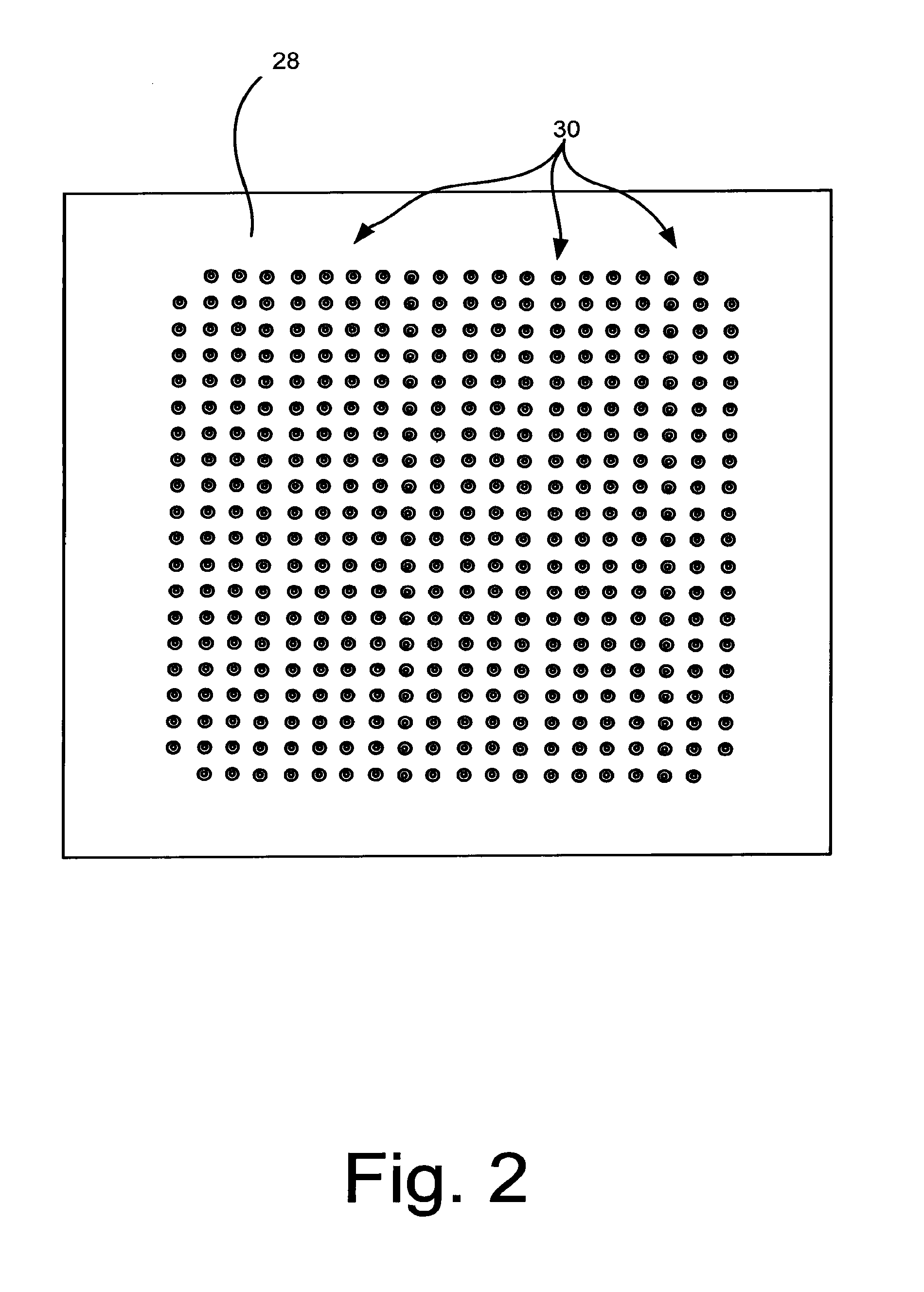
One pattern type that known model training processes are often unable to generate robust models for includes patterns that have repeating elements such as the pattern that results when a ball grid array is imaged.
When one of the training processes described above is used to develop models and a model sequence to be used during a subsequent pattern recognition process where the pattern to be recognized includes repeating elements, the resulting recognition process often results in identification of an incorrect pose (i.e., a pose where the detected pattern instance is misaligned with the actual pattern instance in the image).

Method used


Image

  • Method and Apparatus for Training a Probe Model Based Machine Vision System
  • Method and Apparatus for Training a Probe Model Based Machine Vision System
  • Method and Apparatus for Training a Probe Model Based Machine Vision System

Examples


Embodiment Construction

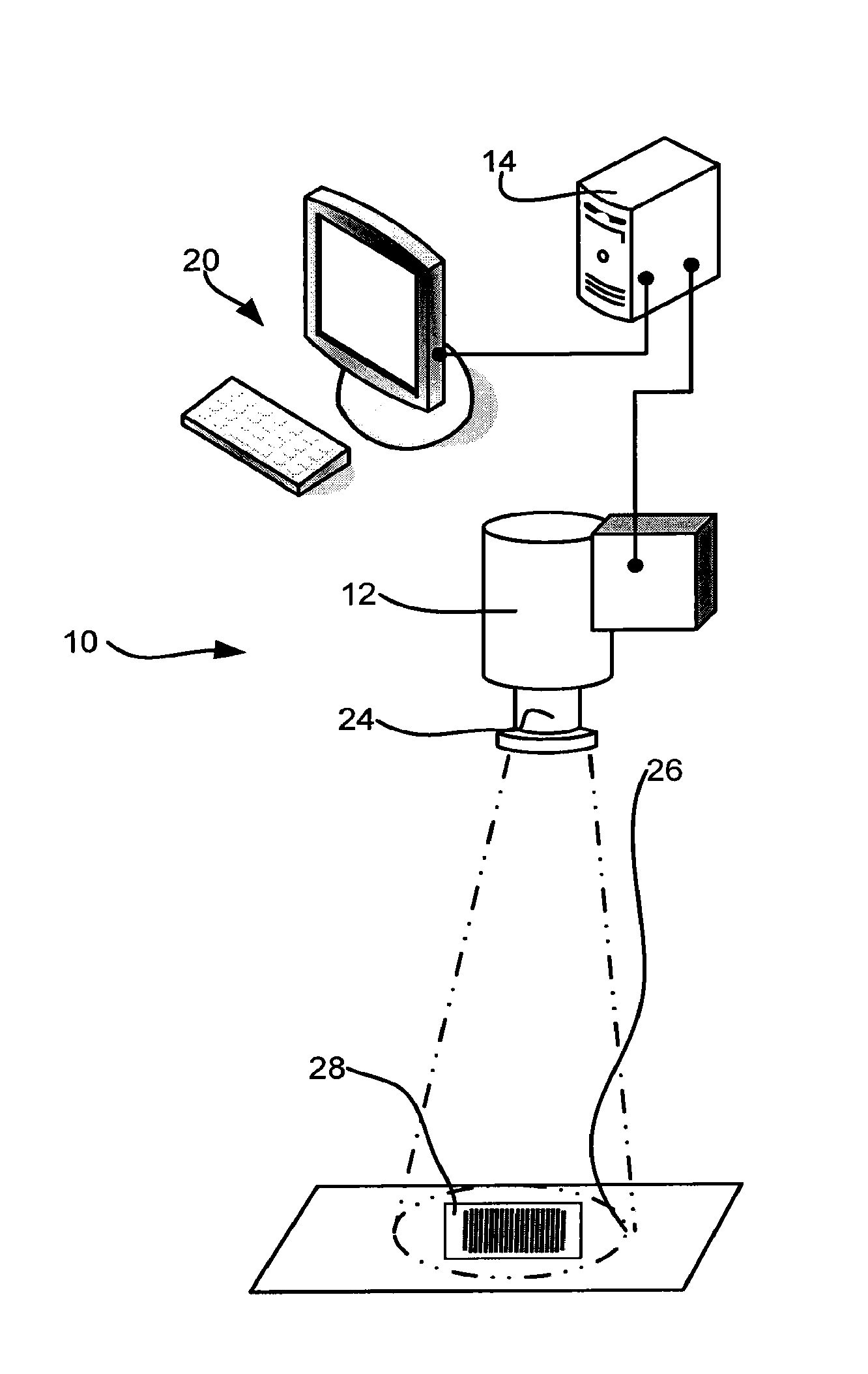
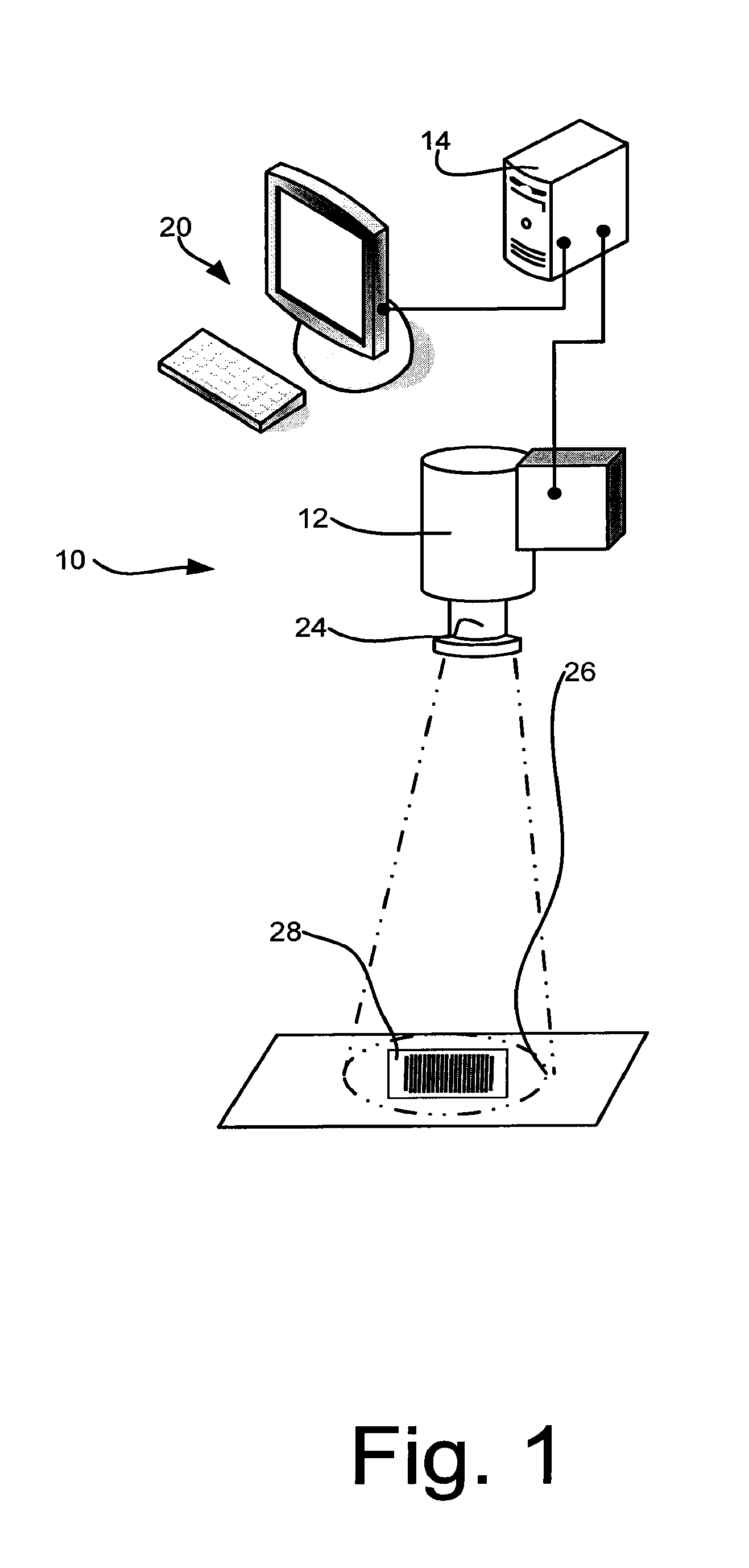
[0080]The various aspects of the subject invention are now described with reference to the related figures, wherein like numerals refer to like or corresponding elements throughout. It should be understood, however, that the drawings and detailed description relating thereto are not intended to limit the claimed subject matter to the particular form disclosed. Rather, the intention is to cover all modifications, equivalents, and alternatives falling within the spirit and scope of the claimed subject matter.

[0081]As used herein, the terms “component,”“system” and the like are intended to refer to a computer-related entity, either hardware, a combination of hardware and software, software, or software in execution. For example, a component may be, but is not limited to being, a process running on a processor, a processor, an object, an executable, a thread of execution, a program, and / or a computer. By way of illustration, both an application running on computer and the computer can b...


PUM


Abstract

A method for training a pattern recognition algorithm including the steps of identifying the known location of the pattern that includes repeating elements within a fine resolution image, using the fine resolution image to train a model associated with the fine image, using the model to examine the fine image resolution image to generate a score space, examining the score space to identify a repeating pattern frequency, using a coarse image that is coarser than the finest image resolution image to train a model associated with the coarse image, using the model associated with the coarse image to examine the coarse image thereby generating a location error, comparing the location error to the repeating pattern frequency and determining if the coarse image resolution is suitable for locating the pattern within a fraction of one pitch of the repeating elements.

Description

CROSS-REFERENCE TO RELATED APPLICATIONS[0001]This application is a continuation of U.S. application Ser. No. 12 / 249,318 which was filed on Oct. 10, 2008 and which is titled “Method and Apparatus for Training a Probe Model Based Machine Vision System”.STATEMENT REGARDING FEDERALLY SPONSORED RESEARCH OR DEVELOPMENT[0002]Not applicable.BACKGROUND OF THE INVENTION[0003]The present invention is related to training algorithms for machine vision systems and more specifically to an iterative process that generates an optimal machine vision process for recognizing a pattern in images.[0004]One task performed by many machine vision systems is to attempt to identify the location and orientation of a pattern of interest within images. Several different classes of algorithms have been developed to perform this pattern locating task.[0005]One advantageous class of such algorithms uses a model to represent the pattern of interest which includes a plurality of probes. Each probe is a measure of sim...

Claims


Application Information

Patent Timeline
Patent Type & Authority Applications(United States)
IPC IPC(8): G06K9/62
CPCG06K9/6256G06K9/3275G06K9/6255G06T2207/30208G06T7/0044G06T2207/20081G06K9/6857G06T7/74G06V10/243G06V30/2504G06V30/1914G06F18/214G06F18/28
Inventor BARKER, SIMON A.WAGMAN, ADAMWALLACK, AARONMICHAEL, DAVID J.
Owner COGNEX CORP
Learn More