
Wireless communication device and wireless communication method

a wireless communication and wireless communication technology, applied in electrical equipment, time-division multiplex, synchronisation arrangement, etc., can solve the problems of increasing cost and not divulging the operation that is performed, and achieve the effect of high reliability

Inactive Publication Date: 2013-07-18
PANASONIC CORP
View PDF7 Cites 4 Cited by
  • Summary
  • Abstract
  • Description
  • Claims
  • Application Information

AI Technical Summary

Benefits of technology

The invention provides a wireless communication device and method for use in a wireless communication system that prevents synchronization issues and is more reliable.

Problems solved by technology

However, this does not disclose an operation that is performed in a case where the relay wireless apparatus is not able to receive the beacon signal from the master wireless apparatus.
However, the technology disclosed in PTL 2 has the following problems and the limitations.
(1) Since both the master wireless apparatus and the slave wireless apparatus need to have a standard radio wave clock function, there is a problem in that an increase in size of a circuit leads to an increase in cost.
(2) Since it is assumed that the actual ranges of communication for the master wireless apparatuses are not overlapped on one another, there is a limitation that the master wireless apparatuses are arranged in such a manner that the beacon signals transmitted from the respective master wireless apparatuses do not interfere with one another.

Method used


Image

  • Wireless communication device and wireless communication method
  • Wireless communication device and wireless communication method
  • Wireless communication device and wireless communication method

Examples


embodiment

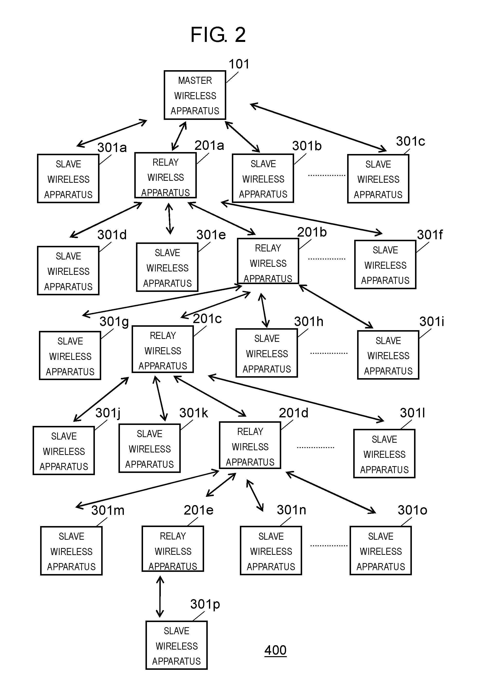
[0041]FIG. 1A is a block diagram illustrating a configuration of master wireless apparatus 101 according to the embodiment of the present invention. FIG. 1B is a block diagram illustrating a configuration of relay wireless apparatus 201 according to the embodiment. FIG. 1C is a block diagram illustrating a configuration of slave wireless apparatus 301 according to the embodiment.

[0042]First, an outline of the configuration of master wireless apparatus 101 is described.

[0043]As illustrated in FIG. 1A, master wireless apparatus 101 includes antenna 1, transmission and reception unit 2, beacon transmission unit 3, link connection unit 4, route information analysis and creation unit 5, control unit 7, timing information transmission unit 6 and storage unit 8.

[0044]Control unit 7 performs time management on entire master wireless apparatus 101 (wireless communication apparatus) and performs control on each unit. Furthermore, control unit 7 functions as a beacon signal creation unit and c...


PUM


Abstract

There is provided a wireless communication apparatus for conducting communication between a high-order apparatus and a low-order apparatus, including a beacon reception unit and a beacon transmission unit. The beacon reception unit receives a first regular beacon signal (351) transmitted from the high-order apparatus. The beacon transmission unit transmits a second regular beacon signal (351) synchronizing a clock of the low-order apparatus to the low-order apparatus in a case where the beacon reception unit receives the first regular beacon signal (351). The beacon transmission unit transmits a temporary beacon signal (352) indicating that the clock of a local station is not able to be synchronized with a clock of the high-order apparatus, to the low-order apparatus, in a case where the beacon reception unit is not able to receive the first regular beacon signal (351).

Description

TECHNICAL FIELD[0001]The present invention relates to a wireless communication system that includes a wireless communication apparatus which transmits a beacon signal and a wireless communication apparatus which establishes clock synchronization by receiving the beacon signal. The present invention particularly relates to a wireless communication apparatus and a wireless communication method used in such a wireless communication system.BACKGROUND ART[0002]In a wireless communication system having a battery-run slave wireless apparatus, the slave wireless apparatus generally awaits reception intermittently to suppress power consumption by the slave wireless apparatus. The wireless communication system called a synchronization type is present as the wireless communication system in which the slave wireless apparatus awaits reception intermittently.[0003]In this system, a master wireless apparatus periodically transmits a beacon signal, and the slave wireless apparatus periodically rec...

Claims


Application Information

Patent Timeline
Patent Type & Authority Applications(United States)
IPC IPC(8): H04W56/00
CPCH04W56/001H04W56/002
Inventor YAMAMOTOHORIIKE, YOSHIOWATANABE, TAKASHI
Owner PANASONIC CORP
Learn More