Fluorescent lamp holder assembly

a fluorescent lamp and assembly technology, applied in the field of electrical engineering, can solve the problems of loosening from the socket, difficult installation or replacement of the lamp, and difficulty in special cases, and achieve the effects of improving the retaining force, simplifying design and assembly, and robust construction

Active Publication Date: 2013-07-18
KHANAMPORNPAN VIROJ
View PDF7 Cites 4 Cited by
  • Summary
  • Abstract
  • Description
  • Claims
  • Application Information

AI Technical Summary

Benefits of technology

[0015]In a preferred embodiment of the invention, the locking means further comprises a lever arm projecting from said pivoting zone opposite to said cantilever arm to operate said cantilever arm between said opening and said locking positions. This makes it possible to obtain increased retaining forces without the user exerting considerable force in order to release the locking means.
[0016]Preferably said locking means further comprises a tongue projecting from said lever ar

Problems solved by technology

In both types of fluorescent lamp holder assemblies, the installation or replacement of the lamp requires a certain skill and it becomes especially difficult when these operations must be done at a certain height, for example at the top of a ladder.
However, this solution has the problem, that the holder can loosen from the socket and thus the fluorescent lamp can fall down.
This solution has the drawback that less pressure can be exerted between the terminals of the socket and the holder and therefore a less reliable electrical contact can be achieved.
Furthermore, if a user tries to replace the lamp by pulling the socket without disengaging the outwardly proje

Method used


Image

  • Fluorescent lamp holder assembly
  • Fluorescent lamp holder assembly
  • Fluorescent lamp holder assembly

Examples


first embodiment

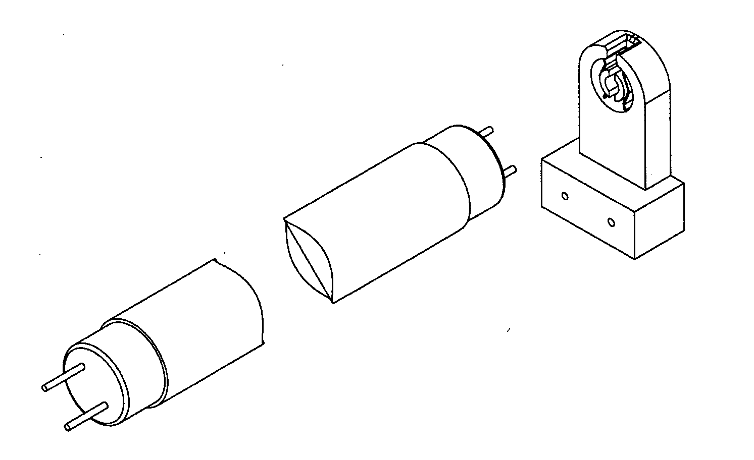
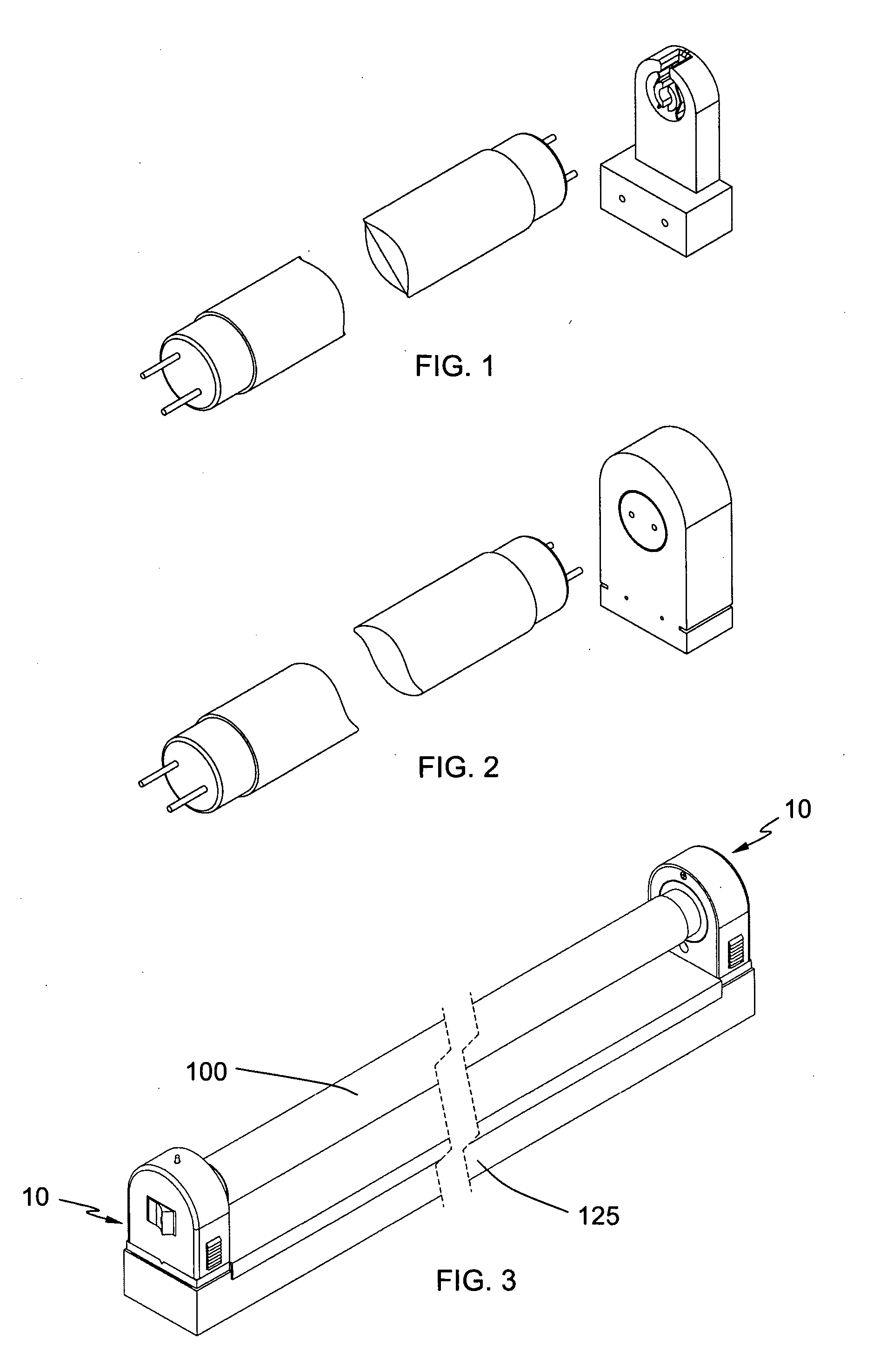
[0044]FIGS. 3 to 5 show the lamp holder assembly according to the invention.

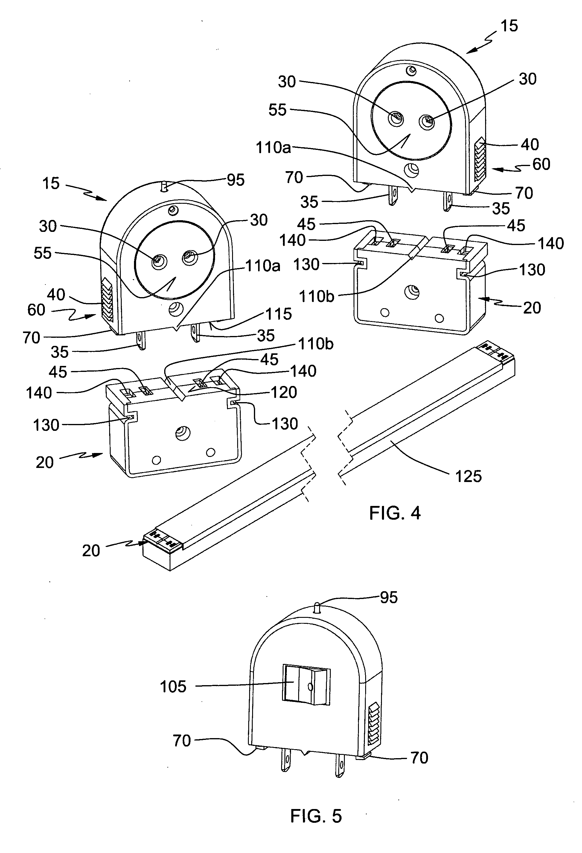
[0045]As can be seen, the fluorescent lamp holder assembly 10 comprises generally a lamp holder 15 and socket 20.

[0046]The lamp holder 15 has a body which houses a pair of electrical terminals and a pair of openings 30 leading to the electrical terminals on the wall 55 of the lamp holder 15 on which the fluorescent lamp 100 is to be plugged in. Further, the lamp holder 15 has a pair of parallel spaced-apart protruding legs 35 of which one end is connected to the terminal and the free end protrudes from the body in the direction of the socket 20.

[0047]On the other hand, the socket 20, which is fixed to the lighting fixture 125 via lateral recesses 130 guided in corresponding rails in the lighting fixture 125, also has a pair of spaced-apart electrical terminals. As it is apparent to the skilled person, the lateral recesses 130 are one of the several ways of attaching the socket 20 to the lighting fixture 125 ...

third embodiment

[0058]FIGS. 15 and 16 show the lamp holder assembly 10 of the invention. Again, almost all the features have already been explained before. However, in this case the lamp holder 15 is provided with rounded cross section legs 35. This solution provides a robuster construction of the holder 15 and thus increases the durability of the lamp holder assembly 10. On the other hand, FIG. 16 shows that the socket 20 of this embodiment comprises insertion inlets 45 adapted to receive both flat and rounded cross section holder 15 legs 35. In this way production and logistic costs can be noticeably reduced, because one single socket 20 serves for different holder types.

[0059]Finally, FIGS. 17 and 18 show a further embodiment of the lamp holder assembly 10 of the invention. In this case, further to the general features already explained in FIGS. 4 to 6B, the lamp holder assembly 10 has the two operable cantilever arms 65 pivotally arranged on the side walls 135 of the holder 15 with a side proje...


PUM


Abstract

Fluorescent lamp holder assembly (10) comprising a lamp holder (15) and a socket (20). The holder (15) houses one pair of electrical terminals, and includes one pair of openings (30) located at a position corresponding to the position of the electrical terminals. The lamp holder (15) includes one pair of parallel spaced-apart legs (35) with one end connected to the terminal and the free end protruding from the body of the holder (15). The socket (20) has one pair of spaced-apart electrical terminals defining insertion inlets (45). The holder (15) can be coupled to the socket (20) by inserting the legs (35) into the corresponding terminals of the socket (20). The holder assembly (10) further comprises releasable, resiliently biased locking means movable between an opening position, in which holder (15) and socket (20) can be unplugged and a locking position, in which holder (15) and socket (20) are held together.

Description

BACKGROUND OF THE INVENTION[0001]The present invention relates to electrical engineering, in particular to a lamp holder and more particularly to a tubular fluorescent lamp holder according to the preamble of claim 1. The two most common fluorescent lamp holder assemblies for by-pin fluorescent lamps are the so-called “twisted type” and “spring type”.[0002]In the “twisted type” lamp holder assembly shown in FIG. 1, during the installation of the lamp, the pins at both ends of the fluorescent lamp must first be introduced into radial grooves in the lamp holder adapted to receive these pins and then the lamp must be twisted about 90 degrees around its longitudinal axis to complete the installation.[0003]In the “spring type” lamp holder assembly shown in FIG. 2, during installation of a lamp, the pins on one end of the lamp are inserted first into a pin dock of the lamp holder provided with a spring. Then, the spring must be pressed inwards, and afterwards the other end follows the sam...

Claims


Application Information

Patent Timeline
IPC IPC(8): F21V19/00
CPCH01R13/6273F21V19/0005H01R13/6395H01R13/6275F21V23/06F21K9/20F21K9/27H01R33/0881H01R13/627F21V23/04
Inventor KHANAMPORNPAN, VIROJ
Owner KHANAMPORNPAN VIROJ
Why Eureka
Try Eureka